Notes-Part-1
|
Topics to be Learn : Part-1
|
Introduction:
- Light travels in a straight line while travelling through a uniform and homogeneous medium.
- Ray of light : A ray of light is the path along which light energy is transmitted from one point to another in an optical system.
- On encountering an interface with another medium, a ray of light gets reflected or refracted, changes its direction and moves along another straight line.
- Reflection of light produced by spherical mirrors and refraction of light through prisms and curved surfaces of lenses.
- The position and nature of the image (whether real or virtual) depend on the position of objects and the focal length of the mirror or lens.
Nature of Light :
The various theories of the nature of light from the 17th century to the modern times are
- Descartes’ corpuscular theory of light (1637)
- Newton's corpuscular theory (1666)
- Huygens’ wave theory of light propagation (1678), modified, verified and put on a firm mathematical base by Young, Fraunhofer, Fresnel and Kirchhoff (in the 1800s)
- Maxwell's electromagnetic theory (1865)
- The light quantum, i.e., the photon model of the modern quantum theory by Planck (1900) and Einstein (1905).
Corpuscular Nature:
Corpuscular theory assumed that light consists of a stream of corpuscles emitted by a luminous source.
Sir Isaac Newton developed the corpuscular theory of light proposed by Rene Descartes (1596-1650), French philosopher and mathematician.
Postulates of Newton's corpuscular theory of light:
- Light is made up of particles, i.e., corpuscles which are hard, elastic and massless.
- A luminous source emits light corpuscles in all directions which then travel at high speed in straight lines in a given medium.
- The constituent colours of white light are due to different sizes of the corpuscles.
- The light corpuscles stimulate the sense of sight on their impact on the retina of the eye.
- A reflective surface exerts a force of repulsion normal to the surface on the light corpuscles when they strike the surface.
- A transparent medium exerts a force of attraction normal to the surface on the light corpuscles striking the surface. This force is different for different mediums.
Drawbacks of Newton's corpuscular theory of light :
- The theory predicted that the speed of light in a denser medium should be greater than that in air. This was disproved when experiment showed that the speed of light in water is less than that in air (carried out in 1850 by French physicist Jean Bernard Le'on Foucault).
- The theory could not satisfactorily explain the phenomenon of polarization and the simultaneousness of reflection and refraction.
- The corpuscular theory failed to explain the phenomena of diffraction and interference.
- There was no basis for the hypothesis that the constituent colours of white light are due to different sized corpuscles.
Ray optics or geometrical optics : The formation of (i) shadows, and (ii) images by mirrors and lenses can be explained by assuming that light propagates in a straight line in terms of rays. The study of optical phenomena under this assumption is called ray optics. It is also called geometrical optics as geometry is used in this study.
Wave Nature:
Huygens’ wave theory of light [Christiaan Huygens (1629-95), Dutch physicist] :
- Light emitted by a source propagates in the form of waves. Huygens’ original theory assumed them to be longitudinal waves.
- In a homogeneous isotropic medium, light from a point source spreads by spherical waves.
- It was presumed that a wave motion needed a medium for its propagation. Hence, the theory postulated a medium called luminiferous ether that exists everywhere, in vacuum as well as in transparent bodies. Ether had to be assigned some extraordinary properties, a high modulus of elasticity (to account for the high speed of light), zero density (so that it offers no resistance to planetary motion) and perfect transparency.
- The different colours of light are due to different wavelengths.
Merits and Demerits of theory :
| Merits | Demerits |
| 1-Huygens’ wave theory satisfactorily explains reflection and refraction as well as their simultaneity.
2-In explaining refraction, the theory concludes that the speed of light in a denser medium is less than that in a rarer medium, in agreement with experimental findings. 3-The theory was later used by Young in 1800-04, Fraunhofer and Fresnel in 1814 to satisfactorily explain interference, diffraction and rectilinear propagation of light. The phenomenon of polarization could also be explained considering the light waves to be transverse. |
1-It was found much later that the hypothetical medium, luminiferous ether, has no experimental basis. Einstein discarded the idea of ether completely in 1905. 2-Phenomena like absorption and emission of light, photoelectric effect and Compton effect, cannot be explained on the basis of the wave theory. To decide between the particle and wave theories of light, Dominique Francois Jean Arago (1786—1853), French physicist, suggested the measurement of the speed of light in air and water. The experiment was performed in 1850 by Léon Foucault (1819-68), French physicist, using Arago’s experimental equipment. He found that the speed of light in water is less than that in air. |
Wave optics :
It is not possible to explain certain phenomena of light, such as interference, diffraction and polarization, with the help of ray optics (geometrical optics).
The branch of optics which uses wave nature of light to explain these optical phenomena is called wave optics.
Maxwell's concept of light :
In 1865, James Clerk Maxwell developed a mathematical theory on the intimate relationship between electricity and magnetism. His theory predicted :
- Light to be a high-frequency transverse electromagnetic wave in ether.
- Electric and magnetic fields in the wave vary periodically in space and time at right angles to each other and to the direction of propagation of the wave.
The speed of the electromagnetic waves in a medium, as calculated on the basis of Maxwell's theory, was experimentally found to be equal to the measured speed of light in that medium.
Maxwell's electromagnetic theory of light, with addition by others till 1896, could account for all the known phenomena regarding the propagation (or transmission) of light through space and through matter.
Dual Nature of Light:
Photon model or quantum hypothesis of light :
To explain the interaction of light and matter (as in the emission or absorption of radiation), Max Planck, in 1900, and Einstein, in 1905, hypothesized light as concentrated or localized packets of energy. Such an energy packet is called a quantum of energy, which was given the name photon much later, in 1926, by Frithiof Wolfers and Gilbert Newton Lewis.
For a radiation of frequency v, a quantum of energy is hv, where h is a universal constant, now called Planck's constant.
Light as a wave :
Wave nature of light :
- Light is a transverse, electromagnetic wave.
- A light wave consists of oscillating electric and magnetic fields that are perpendicular to each other and also perpendicular to the direction of propagation of the wave.
- Like all other electromagnetic waves, light waves do not require any material medium as they can travel even through vacuum.
- In a material medium, the speed of light depends on the refractive index of the medium, which, in turn depends on the permeability and permittivity of the medium.
Refractive index : The speed of light in a material medium (v) depends on the refractive index of the medium (n) which, in turn, depends on permeability and permittivity of the medium.
Absolute refractive index of a medium : The absolute refractive index of a medium is defined as the ratio of the speed of light in vacuum to the speed of light in the medium.
Absolute refractive index of a medium (n) = \(\frac{\text{Speed of light in vaccum}}{\text{speed of light in the medium}}\)
The refractive index of vacuum is 1 and that of air can be approximated to be 1.
Characteristics of the electromagnetic waves :
- The electromagnetic waves are transverse in nature as they propagate by oscillating electric and magnetic fields that are perpendicular to each other and also perpendicular to the direction of propagation of the wave.
- These waves do not require any material medium for their propagation, i.e., they can travel even through vacuum.
- The wavelength of the electromagnetic waves ranges from very small ( < 1 fm) to very large (> 1 km). The waves are classified in the order of increasing wavelength as y-rays, X rays, ultraviolet, visible, infrared, microwave and radio waves.
- In vacuum, the speed of electromagnetic waves does not depend on the frequency of the wave. But, in a material medium, it depends on the frequency.
- For a given frequency, the speed is different in different mediums.
[1 fm (femtometre) = 10-15 m]
Reason for formation of a spectrum and of a rainbow, when white light is passed through a transparent medium :
White light consists of waves of different wavelengths. The refractive index of a medium is different for different wavelengths. Except for normal incidence, for the same angle of incidence, rays corresponding to different colours have different angles of refraction. Hence, when white light passes through a transparent medium, the different colours get separated and spectrum is formed.
Huygens’ Theory:
Primary and Secondary Sources of Light:
The Sun, moon, stars, light bulb, etc. are the several sources of light around us, These can be classified into primary and secondary sources of light.
Primaly sources of light :The sources that emit light on their own are called primary sources. This emission of light may be due to
- the high temperature of the source, e.g., the Sun, the stars, objects heated to high temperature, a flame, etc.
- the effect of current being passed through the source, e.g., tubelight, TV, etc.
- chemical or nuclear reactions taking place in the source, e.g., firecrackers, nuclear energy generators, etc.
Secondary sources of light : Some sources are not self luminous, i.e., they do not emit light on their own, but reflect or scatter the light incident on them. Such sources of light are called secondary sources, e.g. the moon, the planets, objects such as humans, animals, plants, etc. These objects are visible due to reflected light.
Many of the sources that we see around are secondary sources and most of them are extended sources.
Wavefront :
Wavefront or wave surface : The locus of all points where waves starting simultaneously from a source reach at the same instant of time and hence the particles at the points oscillate with the same phase, is called a wavefront or wave surface.
Wavefront related to rays of light :
Consider a point source of light O in a homogeneous isotropic medium in which the speed of light is v. The source emits light in all directions. In time t, the disturbance (light energy) from the source, covers a distance vt in all directions, i.e, it reaches out to all points which are at a distance vt from the point source. The locus of these points which are in the same phase is the surface of a sphere with the centre O and radius vt. It is a spherical wavefront.
Click here to View Figure-1
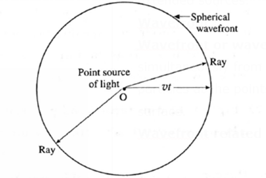
In a given medium, a set of straight lines can be drawn which are perpendicular to the wavefront.
According to Huygens, these straight lines are the rays of light. Thus, rays are always normal to the wavefront. In the case of a spherical wavefront, the rays are radial.
Shape of the wavefront at a point far away from the source of light :
If a wavefront has travelled a large distance away from the source, a small portion of this wavefront appears to be plane. This part is a plane wavefront.
Wavenormal and Ray of light :
| Wavenormal | Ray of light |
| A wavenormal at a point on a wavefront is defined as a line drawn perpendicular to the wavefront in the direction of propagation of the wavefront.
In a homogeneous isotropic medium, a wavefront moves parallel to itself. Thus, at any point in the medium, the direction in which the wavefront moves is always perpendicular to the wavefront at that point. This direction is given by the wavenormal at that point. |
The direction in which light is propagated is called a ray of light.
This term (ray of light) is also used to mean a narrow beam of light waves. Only in a homogeneous isotropic medium is a ray of light the same as a wavenormal. For spherical wavefronts spreading out from a point source, the rays are radially divergent. The rays corresponding to a plane wavefront form a parallel beam. |
Cylindrical wavefront :
- An extended linear source, such as an aperture in the form of a narrow slit, gives rise to cylindrical wavefronts.
- All the points equidistant from the source lie on the curved surface of a cylinder. Thus, the shape of the wavefront is cylindrical.
Click here to View Figure-2

Plane wavefront ; It may be treated as a part of a spherical or cylindrical wavefront at a very great distance from the source, such that the wavefront has a negligible curvature. See Fig.
Click here to View Figure-3
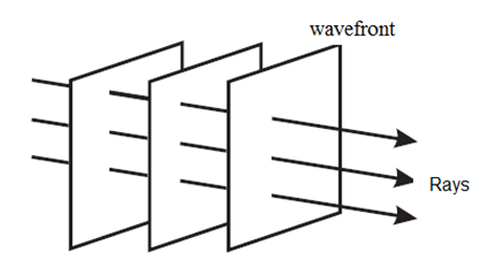
Wavefronts for a plane wave are shown in Fig, where the arrows (rays) which are now parallel corresponding to a parallel beam of light, show the direction of propagation of the wave. If the source of light is linear (along a line) the wave fronts will be cylindrical.
Spherical wavefronts corresponding to diverging beam of light :
Click here to View Figure-4
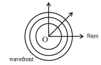
Lenses can be used to obtain (i) a converging beam of light (ii) a diverging beam of light
Huygens’ principle :
Every point on a wavefront acts as a secondary source of light and sends out secondary wavelets in all directions. The secondary wavelets travel with the speed of light in the medium. These wavelets are effective only in the forward direction and not in the backward direction. At any instant, the forward-going envelope or the surface of tangency to these wavelets gives the position of the new wavefront at that instant.
Huygens’ construction of a plane wavefront : A plane wavefront may be treated as a part of a spherical or cylindrical wave at a very great distance from a point source or an extended source, such that the wavefront has a negligible curvature.
Let us first consider a plane wavefront AB (corresponding to parallel rays), at time t = 0 cross section of which is shown in above Fig..
Click here to View Figure-5
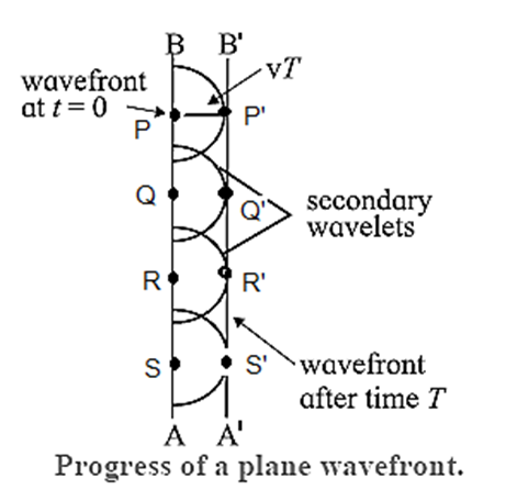
Let P, Q, R, S, ..., be points on a plane wavefront in a homogeneous isotropic medium in which the speed of light, taken to be monochromatic, is v (Fig.).
In a time, t= T, secondary wavelets with points P, Q, R, S,..., as secondary sources travel a distance vT. To find the position of the wavefront after a time t = T, we draw spheres of radii vT with P, Q, R, S,..., as centres. The envelope or the surface of tangency to these spheres is a plane P’Q’R’S’. This plane, the new wavefront A’B’, is at a perpendicular distance vT from the original wavefront in the direction of propagation of the wave. Thus, in an isotropic medium, plane wavefronts are propagated as planes.
Huygens’ construction of a spherical wavefront :
Consider a point source of monochromatic light S in a homogeneous isotropic medium. The light waves travel with the same speed v in all directions. After time t, the wave will reach all the points which are at a distance vT from S. This is spherical wavefront XY. Let, A, B, C, ...,, be points on this wavefront.
Click here to View Figure-6
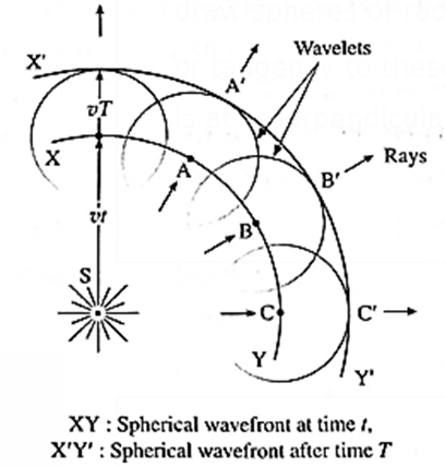
To find the new wavefront after time T, we draw spheres of radius vT with A, B, C,… as centres. The envelope or the surface of tangency of these spheres is the surface A’B’C’. This is the new spherical wavefront X’Y’. Thus, in an isotropic medium, spherical wavefronts are propagated as concentric spheres.
Reflection of light at a plane surface :
Laws of reflection of light using Huygens’ principle :
Consider a plane wavefront AB of monochromatic light incident obliquely at an angle i on a plane mirror MN. The wavefront AB touches the reflecting surface MN at A at time t = 0. Let v be the speed of light in the medium.
When wavefront AB is incident on the mirror, at first, point A becomes a secondary source and emits secondary waves in the same medium. If T is the time taken by the incident wavefront to travel from B to C, then BC = vT. During this time, the secondary wave originating at A covers the same distance, so that the secondary spherical wavelet has a radius vT at time T.
Click here to View Figure-7
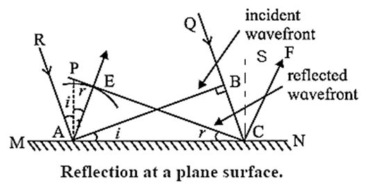
To construct the reflected wavefront, a hemisphere of radius vT is drawn from point A Draw a tangent EC to the secondary wavelet.
As all points on EC are in the same phase of wave motion, EC represents the reflected wavefront.
The arrow AE shows the direction of propagation of the reflected wave.
AP is the normal to MN at A,
∠ RAP = i = angle of incidence and
∠ PAE = r = angle of reflection
In Δ ABC and Δ AEC,
AC is common,
AE =BC and ∠ ABC = ∠ AEC = 90°
Δ ABC and Δ AEC are congruent.
∠ ACE = ∠ BAC = i …….(1)
Also, as AE is perpendicular to CE and AP is perpendicular to AC,
∠ ACE = ∠ PAE =r ...(2)
From Eqs (1) and (2),
i = r
Thus, the angle of incidence is equal to the angle of reflection. This is the first law of reflection. Also, it can be seen from the figure that the incident ray and reflected ray lie on the opposite sides of the normal to the reflecting surface at the point of incidence and all of them lie in the same plane. This is the second law of reflection. Thus, the laws of reflection of light can be deduced by Huygens’ construction of a plane wavefront.
CE = AB shows that the size of the image equals that of the object. On reflection, A is seen at E and B is seen at C. This is lateral inversion, i.e., on reflection, the right side of an object becomes the left side, and the left side of the object becomes the right side.
Refraction of Light at a Plane Boundary Between Two Media :
Laws of refraction of light using Huygens’ principle
OR
Snell's law of refraction of light on the basis of wave theory :
Consider a plane wavefront AB of monochromatic light propagating in the direction A’A incident obliquely at an angle i on a plane refracting surface MN. This plane refracting surface MN separates two uniform and optically transparent mediums.
Let v1 and v2 be the speeds of light in medium 1 (say, a rarer medium) and medium 2 (a denser medium) respectively.
Click here to View Figure-8
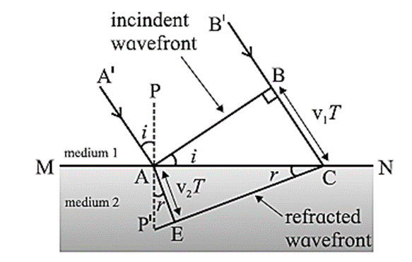
When the wavefront reaches MN at point A at t = 0, A becomes a secondary source and emits secondary waves in the second medium, while ray B’B reaches the surface MN at C at time t = T. Thus, BC = v1T. During the time T, the secondary wavelet originating at A covers a distance AE in the denser medium with radius v2T.
As all the points on CE are in the same phase of wave motion, CE represents the refracted wavefront in the denser medium. CE is the tangent to the secondary wavelet starting from A. It is also a common tangent to all the secondary wavelets emitted by points between A and C. PP’ is the normal to the boundary at A.
∠ A’AP = ∠ BAC = the angle of incidence (i) and
∠ P’AE = ∠ ACE = the angle of refraction (r).
From Δ ABC and Δ AEC,
sin i = \(\frac{BC}{AC}\) and sin r = \(\frac{AE}{AC}\)
∴ \(\frac{sin\,i}{sin\,r}=\frac{BC/AC}{AE/AC}=\frac{BC}{AE}=\frac{v_1T}{v_2T}=\frac{v_1}{v_2}\)
By definition, the refractive index of medium 2 with respect to medium 1,
1n2 = \(\frac{n_2}{n_1}=\frac{v_1}{v_2}\)
∴ \(\frac{n_2}{n_1}=\frac{sin\,i}{sin\,r}\)
n1 sin i = n2 sin r ….. (1)
Here, n1 and n2 are the absolute refractive indices of medium 1 and medium 2 respectively. Eq. (1) is Snell's law of refraction. Also, it can be seen from the figure, that the incident ray and the refracted ray lie on the opposite sides of the normal and all three of them lie in the same plane.
Thus, the laws of refraction of light can be deduced by Huygens’ construction of a plane wavefront.
If v1 > v2, i.e. n1 < n2, then r < i (bending of the refracted ray towards the normal).
Dependence of Wavelength on the Refractive Index of the Medium:
Consider monochromatic light incident normally on a boundary between a rarer medium and a denser medium as shown in Fig. (a).
The boundary between the two surfaces is shown by PQ.
The three successive wavefronts AB, CD and EF are separated by a distance λ1, which is the wavelength of light in the first medium.
After refraction, the three wavefronts are indicated by A′B′, C′D′ and E′F′.
Click here to View Figure-9
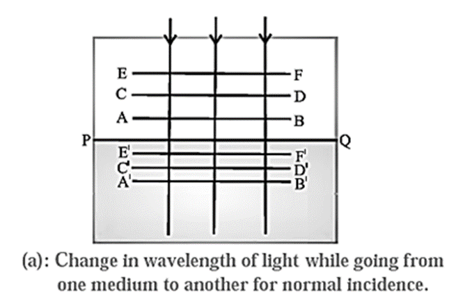
Assuming the second medium to be denser, the speed of light will be smaller in that medium and hence, the wavefronts will move slower and will be able to cover less distance than that covered in the same time in the first medium.
They will therefore be more closely spaced than in the first medium. The distance between any two wavefronts is λ2, equal to the wavelength of light in the second medium. Thus, λ2 will be smaller than the wavelength in the first medium.
We can easily find the relation between λ1 and λ2 as follows.
Let the wavefront AB reach the boundary surface PQ at time t = 0 and the next wavefront CD which is at a distance of λ1 from AB, reach PQ at time t = T. As the speed of the wave is v1 in medium 1 and T is the time period in which the distance λ is covered by the wavefront , we can write
T = λ1/v1 ….(1)
In medium 2, the distance travelled by the wavefront in time T will be λ2. The relation between these two quantities will be given by
T = λ2/v2 …….(2)
Eq. (1) and Eq. (2) show that the velocity in a medium is proportional to the wavelength in that medium and give
λ2 = λ1 v2/ v1 = λ1 n1/n2 ……..(3)
If medium 1 is vacuum where the wavelength of light is λ0 and n is the refractive index of medium 2, then the wavelength of light in medium 2, λ, can be written as
λ = λ0 v2/c = λ0/n …. (4) (… as v1 = c)
The ratio of the frequencies ν1 and ν2, of the wave in the two media can be written, using Eq. (3) as,
ν1/ν2 = (v1/λ1)/(v2/λ2) = 1 …..(5)
This demonstrates that the frequency of a wave remains unchanged while going from one medium to another.
Thus, νo = ν1 = ν2, where νo is the frequency of light in vacuum.
Similar analysis goes through if the wave is incident at an angle as shown in Fig. (b)
Click here to View Figure-10

We have
λ2 = λ1 n1/n2 and ν1 = ν2
| Remember :
The frequency of a wave is its fundamental property and does not change while going from one medium to another. The speed and the wavelength of a wave do change and are inversely proportional to the relative refractive index of the second medium with respect to the first. |
Polarization:
Polarized light :
According to the electromagnetic theory of light, a light wave consists of electric and magnetic fields vibrating at right angles to each other and to the direction of propagation of the wave. If the vibrations of the electric field in a light wave are confined to a single plane containing the direction of propagation of the wave so that its electric field is restricted along one particular direction at right angles to the direction of propagation of the wave, the wave is said to be plane-polarized or linearly polarized.
Unpolarized light :
If the vibrations of in a light wave are in all directions perpendicular to the direction of propagation of the light wave, the light wave is said to be unpolarized. Ordinary light, e.g. that emitted by a bulb, is unpolarized.
According to Biot, unpolarized light may be considered as a superposition of many linearly polarized waves, with random orientations. Also, these component waves are noncoherent, that is, irregular in their phase relationships.
Note : Ordinary light consists of wave trains, each coming from a separate atom in the source. A beam of ordinary light in a single direction consists of millions of such wave trains from the very large number of atoms in the source radiating in that direction. Hence, the vibrations of are in all transverse directions with equal probability. Thus, light from an ordinary source is unpolarized.
Distinguish between polarized and unpolarized light in a ray diagram :
Linearly polarized light is represented in a ray diagram by double-headed arrows or short lines drawn perpendicular to the direction of propagation of light, as shown in Fig. (a).
Click here to View Figure-11 (a) and (b)
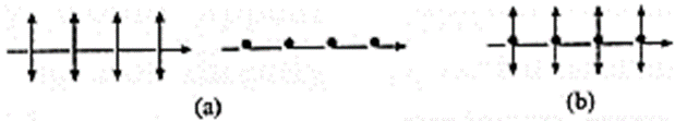
An unpolarized light beam is represented by both dots and arrows, as shown in Fig. (b). The dots are the ‘end views’ of arrows that are oriented normal to the plane of the diagram.
Note : The length of an arrow or line represents the amplitude of the electric field (E ) in the plane of the diagram and the direction indicates the polarization axis of the beam, i.e., the direction of vibration of . According to Jean Biot (1774-1862), French physicist, unpolarized light may be considered as a superposition of many linearly polarized waves, with random orientations in planes perpendicular to the direction of propagation.
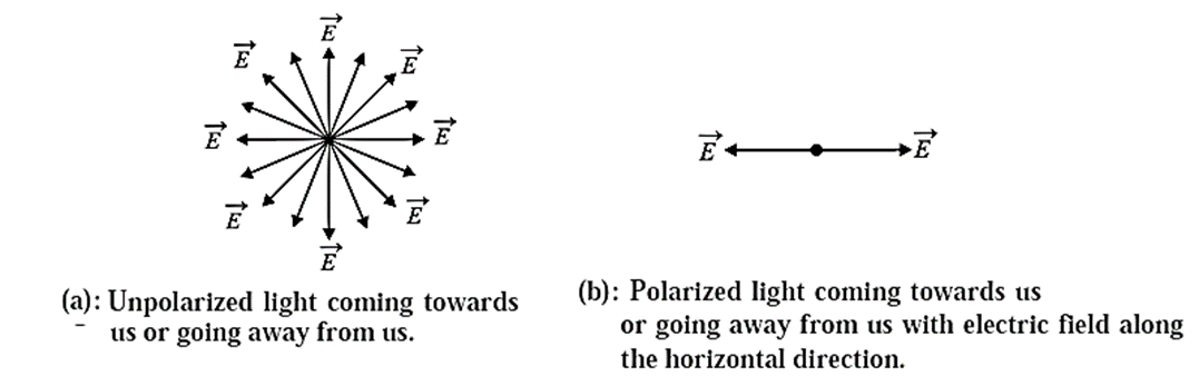
In an analytical treatment, the electric vectors may be resolved along two mutually perpendicular directions so that the multiplicity of vectors in below Fig. (a) can be replaced by the two mutually perpendicular vectors as in below Fig. (b), both perpendicular to the direction of propagation of light. Sir David Brewster (1781-1868), British physicist, conceived the ordinary unpolarized light to consist of two perpendicular, polarized components of equal intensity.
Click here to View Figure-12 (a) and (b)
How can we get polarized light? :
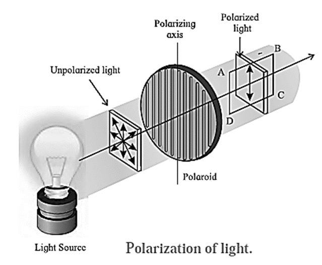
Polarizer : When a beam of unpolarized light is passed through certain types of materials (or devices), these materials (or devices) allow only those light waves to pass through which have their electric field along a particular direction. All the other waves with the electric field in other directions are blocked. A material (or a device) which exhibits this special property is called a polarizer.
Polarizing axis of a polarizer : When unpolarized light is incident on a polarizer, the particular direction along which the electric field of the emergent wave is oriented is called the polarizing axis of the polarizer.
Plane of vibration :The plane of vibration of an electromagnetic wave is the plane of vibration of the electric field vector containing the direction of propagation of the wave. Experiment shows that it is the electric field vector which produces the optical polarization effects.
Plane of polarization : The plane of polarization of an electromagnetic wave is defined as the plane perpendicular to the plane of vibration. It is the plane containing the magnetic field vector and the direction of propagation of the wave.
Click here to View Figure-13

Polaroid : A Polaroid is a synthetic dichroic sheet polarizer packed with tiny dichroic crystals oriented parallel to each other such that the transmitted light is plane polarized.
- Construction :The first large polarizing sheet filter was made by US inventor Edwin H. Land (1909-91). He used the microscopic needlelike crystals of iodoquinine sulphate (known as herapathite) made into a thick colloidal dispersion in nitrocellulose. This material was squeezed through a long narrow slit which forced the needles to orient parallel to one another. The material was then dried to form a solid plastic sheet.
Polarization and Malus’ law : Malus’ law gives the intensity of a linearly polarized wave after it passes through a polarizer.
According to the electromagnetic theory of light, a light wave consists of electric and magnetic fields vibrating at right angles to each other and to the direction of propagation of the wave. If the vibrations of \(\vec{E}\) in a light wave are in all directions perpendicular to the direction of propagation of light, the wave is said to be unpolarized.
If the vibrations of the electric field \(\vec{E}\) in a light wave are confined to a single plane containing the direction of propagation of the wave so that its electric field is restricted along one particular direction at right angles to the direction of propagation of the wave, the wave is said to be plane-polarized or linearly polarized.
This phenomenon of restricting the vibrations of light, i.e., of the electric field vector in a particular direction, which is perpendicular to the direction of the propagation of the wave is called polarization of light.
Click here to View Figure-14
Consider an unpolarized light wave travelling along the x-direction. Let c, n and λ be the speed, frequency and wavelength, respectively, of the wave. The magnitude of its electric field (\(\vec{E}\) ) is,
E = E0 sin (kx − ωt), where E0 = Emax = amplitude of the wave, ω = 2pn = angular frequency of the wave and k = 2p/λ = magnitude of the wave vector or propagation vector.
The intensity of the wave is proportional to |E0|2.
The direction of the electric field can be anywhere in the y-z plane. This wave is passed through two identical polarizers as shown in below Fig.
When a wave with its electric field inclined at an angle Φ to the axis of the first polarizer is passed through the polarizer, the component E0 cos Φ will pass through it. The other component E0 sin Φ which is perpendicular to it will be blocked.
Click here to View Figure-15

Now, after passing through this polarizer, the intensity of this wave will be proportional to the square of its amplitude, i.e., proportional to |E0 cos Φ|2.
The intensity of the plane-polarized wave emerging from the first polarizer can be obtained by averaging |E0 cos Φ|2 over all values of Φ between 0 and 180°. The intensity of the wave will be proportional to ½|E0|2 as the average value of cos2Φ over this range is Thus the intensity of an unpolarized wave reduces by half after passing through a polarizer.
When the plane-polarized wave emerges from the first polarizer, let us assume that its electric field ( ) is along the y-direction. See Fig . Thus, this electric field is,
\(\vec{E}\) =\(\hat{j}\) E10 sin (kx—ωt) …..(1)
where, E10 is the amplitude of this polarized wave.
The intensity of the polarized wave,
I1 ∝ lE10l2 …….(2)
Now this wave passes through the second polarizer whose polarization axis (transmission axis) makes an angle θ with the y-direction. This allows only the component E10 cos θ to pass through it.
Thus, the amplitude of the wave which passes through the second polarizer is
E20 = E10 cos θ and its intensity,
I2 ∝ |E20|2
∴ I2 ∝ |E20|2 cos2θ
∴ I2 = I1 cos2θ ….(3)
Thus, when plane-polarized light of intensity I1 is incident on the second identical polarizer, the intensity of light transmitted by the second polarizer varies as cos2θ, i.e., I2 = I1 cos2θ, where θ is the angle between the transmission axes of the two polarizers. This is known as Malus’ law.
| Remember :
Only transverse waves can be polarized while longitudinal waves cannot be polarized. In transverse waves, the oscillations can be along any direction in a plane which is perpendicular to the direction of propagation of the wave. By restricting the oscillations to be along only one direction in this plane, we get a plane polarized wave. For longitudinal waves, e.g., the sound wave, the particles of the medium oscillate only along one direction, which is the direction of propagation of the wave, so there is nothing to restrict. |
Unpolarized light is passed through two polarizers :
θ = 0° and 90° are known as parallel and cross settings of the two polarizers.
- If the angle θ between the axes of polarization of the two polarizers, is 0°, i.e., the polarization axes of the two polarizers are parallel, the intensity of emergent light is maximum.
- If θ = 90°, i.e., the polarization axes of the two polarizers are perpendicular, no light emerges from the second polarizer, thus the intensity of emergent light is minimum.
Crossed polarizers are a pair of polarizers with their transmission axes perpendicular to each other so that the transmitted light intensity is zero
Use of a pair of polarizers to vary the intensity of light :
Consider an unpolarized light beam incident perpendicularly on the first polarizing sheet, called the polarizer, whose transmission axis is vertical, say.
Click here to View Figure-16
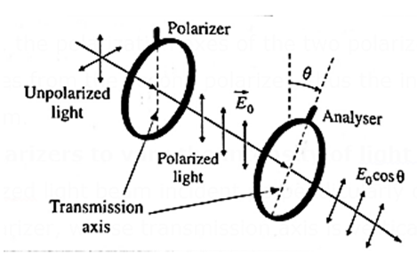
The light emerging from this sheet is polarized vertically, and the transmitted electric field is \(\vec{E_0}\) The polarized light beam then passes through a second polarizing sheet, called the analyser, which is placed parallel to the polarizer with its transmission axis at an angle θ to the transmission axis of the polarizer.
The component of \(\vec{E_0}\) which is perpendicular to the axis of the analyser is completely absorbed, and the component parallel to that axis is E0 cos θ
Since intensity varies as the square of the amplitude, the transmitted intensity varies as
I = I0 cos2θ
where I0 is the incident light intensity on the analyser. This expression (known as Malus’s law) shows that the transmitted intensity is maximum when the transmission axes are parallel and zero when the transmission axes are perpendicular to each other.
Polarization by Reflection: Brewster’s Law:
Consider a ray of unpolarized monochromatic light incident at an angle θB on a boundary between two transparent media as shown in Fig. Medium 1 is a rarer medium with refractive index n1 and medium 2 is a denser medium with refractive index n2. Part of incident light gets refracted and the rest gets reflected. The degree of polarization of the reflected ray varies with the angle of incidence.
The electric field of the incident wave is in the plane perpendicular to the direction of propagation of incident light. This electric field can be resolved into a component parallel to the plane of the paper, shown by double arrows, and a component perpendicular to the plane of the paper shown by dots, both having equal magnitude. Generally, the reflected and refracted rays are partially polarized, i.e., the two components do not have equal magnitude.
Click here to View Figure-17
In 1812, Sir David Brewster discovered that for a particular angle of incidence. θB, the reflected wave is completely plane-polarized with its electric field perpendicular to the plane of the paper while the refracted wave is partially polarized. This particular angle of incidence (θB) is called the Brewster angle.
For this angle of incidence, the refracted and reflected rays are perpendicular to each other.
For angle of refraction θr,
θB + θr = 90° ...(1)
From Snell's law of refraction,
n1 sin θB = n2 sin θr ….(2)
From Eqs. (1) and (2), we have,
n1 sin θB = n2 sin(90°— θB) = n2 cos θB
∴ θB = tan-1\(\frac{n_2}{n_1}\)
This is called Brewster's law.
∴ Brewster's law : The tangent of the polarizing angle is equal to the refractive index of the reflecting medium with respect to the surrounding (1n2).
If θB is the polarizing angle,
tan θB = 1n2 = \(\frac{n_2}{n_1}\)
Here n1 is the absolute refractive index of the surrounding and n2 is that of the reflecting medium.
The angle θB is called the Brewster angle.
Polarizing angle :The polarizing angle for an interface is the angle of incidence for a ray of unpolarized light at which the reflected ray is completely polarized.
At the polarizing angle, the reflected ray is completely plane polarized in the plane of incidence.
Use of polarization by reflection :
Polarization by reflection is used to cut out glare from nonmetallic surfaces. Special sunglasses are used for this purpose. Sunglasses fitted with Polaroids reduce the intensity of partially or completely polarized / reflected light incident on the eyes from reflecting surfaces.
Uses of Polaroid :
- A Polaroid lens filter makes use of polarization by reflection. This filter is used in photography to reduce or eliminate glare from reflective nonmetallic surfaces like glass, rock faces, water and foliage. It can also deepen the colour of the skies.
- Polaroid sunglasses reduce the transmitted intensity by a factor of one half and also reduce or eliminate glare from nonmetallic surfaces such as asphalt roadways and snow fields.
- Polaroid filters are used in liquid crystal display (LCD) screens.
- Polaroids are used to produce and show 3-D movies to give the viewer a perception of depth.
What will you observe :
|
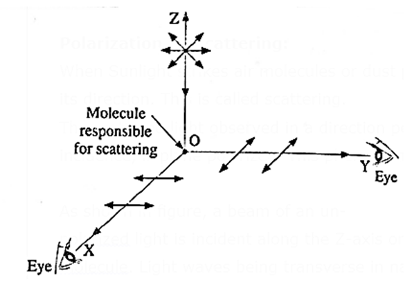
Polarization by Scattering:
When Sunlight strikes air molecules or dust particles in the atmosphere, it changes its direction. This is called scattering.
The scattered light observed in a direction perpendicular to the direction of incidence, is plane polarized. This phenomenon is called polarization by scattering.
Click here to View Figure-18
As shown in figure, a beam of an unpolarized light is incident along the Z-axis on a molecule. Light waves being transverse in nature, all the possible directions of vibration of electric field vector in the unpolarized light are confined to the XY plane. The light incident on the molecule is scattered by the electromagnetic field of the molecule.
When observed along the X-axis, only the vibrations of electric field vector which are parallel to Y-axis can be seen. In the similar manner, when observed along the Y-axis, only the vibrations of electric field vector which are parallel to the X-axis can be seen. Thus, the light scattered in a direction perpendicular to the incident light is plane polarized.
|
It’s amazing as I want … Heartly thanks for this ……