Notes Part-2
Topics to be Learn : Part-2
|
Dispersion of light and prisms:
The phenomenon of separation of the light into its constituent colours is called dispersion.
The colour of light that we see depends upon the frequency of that ray (wave).
The refractive index of a material also depends upon the frequency of the wave and increases with frequency. Refractive index of light is different for different colours. The angular separation between the two extreme rays of different colours in the dispersed beam of a polychromatic light is called the angular dispersion.
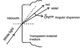
The red light deviates the least while violet the most. Other colours have intermediate deviations.
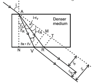
The angular separation between two specified colours, say violet and red, is a measure of the dispersion produced. In above Fig. the angular dispersion (Δ) = δV − δR [= (i − rv) − (i − rR) = (rR − rV)]
Lateral dispersion : When a monochromatic ray of light, obliquely incident on one surface of a parallel-plate glass slab, the ray emerges through the opposite surface parallel to the incident direction but laterally displaced. When a narrow collimated beam of white light in free space or air is obliquely incident on such a glass slab, it passes into the glass with its constituent colours angularly dispersed, (see above Fig.) But as the refracted rays emerge into air through the parallel surface, they undergo deviations equal and opposite to those at the first surface. Hence, the emergent rays of all the colours are parallel to each other and to the incident direction, but laterally displaced with different lateral displacements.
Why a parallel-plale (i.e., rectangular) glass slab cannot be used to observe dispersion :
Explanation :
- If LV and LR are the lateral displacements for violet and red rays, LV — LR is a measure of the lateral dispersion.
- However, since the emergent rays of the constituent colours are all parallel, they will be focused at the same retinal spot of an observer and will be perceived as white light.
- For the observer to discern the constituent colours, the rays of different colours must fall at different spots on the retina. That is, the rays of different colours must be angularly dispersed.
- Thus, for an observer in air to see the colours dispersed, it is necessary that the rays do not emerge parallel to each other which, in turn, necessitates that the emergent surface of the medium is not parallel to the incident surface. Thus, a parallel-plate glass slab cannot be used to observe dispersion.
- A medium whose emergent surface is not parallel to the incident surface is called a prism.
Prism : A prism is a block of transparent medium bounded by usually three plane faces.
Refracting faces of a prism : The refracting faces of a prism are two of its plane faces which are highly polished, and form the incident and the emergent faces of the prism. (The third face, called the base of the prism, is grounded or left unpolished)
Refracting edge of a prism : The retracting edge of a prism is the straight edge at which the two retracting faces of the prism meet.
Principal section of a prism : The principal section of a prism is the transverse section of the prism perpendicular to its refracting edge.
Refracting angle of a prism : The refracting angle A of a prism is the included angle between the two refracting faces of the prism.
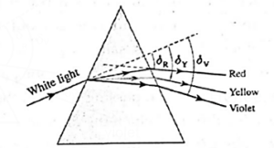
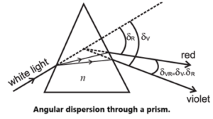
Dispersion of while light produced by a prism :
δR, δY and δV E= deviation angles for extreme red, mean yellow and extreme violet, respectively. Angular dispersion, Δ = δV — δR
Relations between the angles involved:
Consider a principal section ABC of a triangular prism (refractive index, n2) surrounded by a medium 1 (n1). Let n2 > n1.
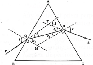
Figure shows a monochromatic ray of light passing through the prism.
Ray PQ is incident on the refracting face AB at an angle of incidence i and r1 is the angle of refraction.
Ray QR, the refracted ray inside the prism, is then incident on the second refracting face AC at an angle of incidence r2.
RS is the emergent ray and e the angle of emergence. The ray suffers deviation
δ1 and δ2 at the two faces AB and AC, respectively, and δ is the total deviation.
QM and RM are the normals to the two refracting faces at points Q and R, respectively.
The rays PQ and SR are produced to meet at T.
Since, ∠AQM = ∠ ARM = 90°, AQMR is a cyclic quadrilateral.
∠A + ∠QMR = 180° ……..(1)
Also, from ΔQMR,
r1 + r2 + ∠QMR = 180° …….(2)
Therefore, from Eqs. (1) and (2),
A = r1 + r2 ……(3)
From the diagram,
i = ∠TQM = δ1 + r1 and
e = ∠TRM = δ2 + r2 ... (opposite angles)
∴ δ1 = i − r1 and δ2 = e − r2
δ is the exterior angle of ΔQTR, so that
δ = δ1 + δ2 …..(interior opposite angles)
∴ δ = i + e − (r1 + r2) …….(4)
so that, from Eq. (3),
δ = i + e − A
∴ i + e = A + δ
For a ray of light passing through a prism, suffers the same deviation for two angles of incidence :
Explanation :
Consider a monochromatic ray of light through a prism along the path PQRS, Fig.

The angle of incidence on the face AB of the prism is i1 = i and the angle of emergence at the face AC is e.
- According to the principle of reversibility of light-path, if a ray proceeds from a point P to a point S by following a particular path after any number of reflections and refractions, then if the ray is allowed to start from S it will trace the same path back to P, provided the conditions under which reflections and refractions occurred remain the same.
- So, if a plane mirror is held perpendicular to the ray R5 then, according to the above principle, the ray will trace the path back as SRQP, as shown in Fig. Its angle of incidence on face AC is i2 = e and angle of emergence at the face AB is i1. The angle of deviation δ, however, remains the same as before. Thus, for two values of angles of incidence i1 and i2, a ray suffers the same deviation.
Deviation curve, minimum deviation and prism formula::
For refraction of a monochromatic ray of light through a prism, as the angle of incidence is increased from a low value, the angle of deviation initially decreases and then increases after going through a minimum value δM called the angle of minimum deviation. Therefore, the graph of the angle of deviation δ against the angle of incidence i is a nearly parabolic curve, Fig. such that the same δ occurs for two values of angle of incidence, i1 and i2 (i1 = i0, and i2 > i0).
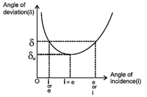
The graph clearly shows that the minimum value of δ, δM, occurs for a single value of the angle of incidence in, which implies that the angle of incidence is equal to that angle of emergence :
i = e ( = i0)
Then, by Snell's law, r1 = r2 ( = r, say)
Therefore, from the prism relations,
A = r1 + r2 and i + e = A + 6,
A = 2r or r = A/2
And 2i0 = A + δM or i0 = \(\frac{A+δ_M}{2}\)
The refractive index of the material of the prism with respect to the surrounding medium.
1n2 = \(\frac{sin\,i_0}{sin\,r}\) = \(\frac{sin\frac{A+δ_M}{2}}{sin\frac{A}{2}}\)
This is the prism formula.
Thin prisms:
Prisms having refracting angle less than 100 (A < 100 ) are called thin prisms.
A is usually between 2° and 5°. The angle of minimum deviation δM for
such a prism is also equally small.
The prism formula for any prism in general, is
1n2 = \(\frac{sin\frac{A+δ_M}{2}}{sin\frac{A}{2}}\) ….(1)
For very small angles, the sine of an angle is approximately equal to the angle in radian.
Hence, for a thin prism we can write \(sin\frac{A+δ_M}{2}=\frac{A+δ_M}{2}\) and \(sin\frac{A}{2}=\frac{A}{2}\)
Therefore, Eq. (1) becomes
1n2 = \(\frac{\frac{A+δ_M}{2}}{\frac{A}{2}}\) .....(2)
∴ A(1n2) = A + δM or δ = A(1n2 - 1)
where the subscript M has been dropped because a thin prism is almost exclusively used at minimum deviation.
Angular dispersion and mean deviation:
If a polychromatic beam is incident upon a prism, the emergent beam consists of all the individual colours angularly separated. This is angular dispersion.
Suppose, for two colours 1 and 2, the material of a thin prism has refractive indices n1 and n2 with n2 > n1. Let the deviations for the two colours be δ1 and δ2, respectively. For a thin prism,
δ = A(n - 1)
δ2 > δ1 for n2 > n1
∴ Angular dispersion for the two colours,
δ21 = δ2 — δ1 = A (n2—1)—A (n1—1)
= A (n2 — n1)
Dispersive power:
- Ability of an optical material to disperse constituent colours is its dispersive power.
- It is measured for any two colours as the ratio of angular dispersion to the mean deviation for those two colours.
Expressions for dispersive power of a transparent material in terms of angles of deviation and refractive indices :
When white light is dispersed, the deviation is maximum for the extreme violet ray (δV) and minimum for the extreme red ray (δR). The deviation for yellow ray δY is approximately intermediate between them. Then, the angular dispersion between the rays of the extreme colours is Δ = δV — δR
∴ The dispersive power of the material of the prism is
ω = (angular dispersion)/(angle of deviation of mean colour)
= \(\frac{Δ}{δ_Y}=\frac{δ_V-δ_R}{δ_Y}\) …..(1)
Let nV, nR and nY be the refractive indices of the material of the prism for violet, red and yellow light, and δV, δR and δY be the corresponding angles of minimum deviation, respectively.
For a thin prism, δ = A(n — 1)
∴ δV = A(nV — 1), δR = A(nR — 1) and δY = A(nY — 1)
Then, from Eq. (1),
ω = \(\frac{Δ}{δ_Y}=\frac{δ_V-δ_R}{δ_Y}\)
∴ ω = \(\frac{A(n_V-n_g)}{A(n_Y-1)}=\frac{n_V-n_g}{n_Y-1}\) …..(2)
Equations (1) and (2) give the required expressions.
- As ω is the ratio of same physical quantities, it is unitless and dimensionless quantity.
- From the expression in terms of refractive indices it should be understood that dispersive power depends only upon refractive index (hence material only) and not upon the dimensions of prism. For commonly used glasses it is around 0.03.
Some natural phenomena due to Sunlight:
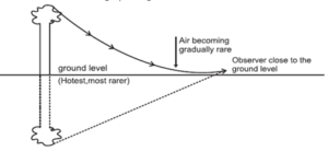
Mirage: On a hot clear Sunny day, along a level road, a pond of water appears to be there ahead. However, if we physically reach the spot, there is nothing but the dry road and water pond again appears ahead. This illusion is called a mirage.
Reason :
- When the Sun heats the Earth's surface, a layer of hot air with a lower mass density (and refractive index) is sometimes created right at the surface. The air layers away from the surface become progressively cooler.
- When the vertical temperature gradient is steep, the optically rarer patch of hot air just above the Earth's surface may constantly refract a beam of light back up into the denser air above, as seen in Fig.
- An inverted picture, produced beneath the true location of the actual object, creates the illusion of the object being reflected in a pool of water.
- To see a mirage one must be looking down a featureless surface such as that of a desert or asphalt pavement of a highway on a calm sunny day.
Rainbow :
- A rainbow is a large-scale dispersion event in nature that occurs when water droplets in the air or in rain-bearing clouds divide sunlight into its constituent colors.
- Rainbows appear as arcs of the spectrum across the sky when the Sun is behind the viewer.
- Rainbows are caused by the refraction, dispersion, and internal reflection of sunlight by water drops.
- When there are two bows visible, the inner bow is referred to as the primary bow.
- The secondary bow is the outer bow in which the colors are inverted in relation to the primary bow.
Some facts to know about rainbow :
- It is seen during rains and on the opposite side of the Sun.
- It is seen only during mornings and evenings and not throughout the day.
- In the commonly seen rainbow red arch is outside and violet is inside.
- In the rarely occurring concentric secondary rainbow, violet arch is outside and red is inside.
- It is in the form of arc of a circle.
- Complete circle can be seen from a higher altitude, i.e., from an aeroplane.
Conditions necessary for formation of a rainbow:
- Light shower with relatively large raindrops, morning or evening time and enough Sunlight.
- The sun must not be more than 42° above the horizon. Thus, it is possible to see a rainbow in the morning a few hours before noon and in the afternoon a few hours afternoon.
- The sun must be behind the observer and not obscured by clouds.
Formation of a primary rainbow :
A rainbow is caused by the dispersion of the sunlight into its constituent colours by the water droplets present in the clouds. The brighter rainbow usually seen is the primary rainbow. At each water drop, the sunlight refracts into it, gets internally reflected once and emerges out with a second refraction.
As shown in Fig. the deviation at each refraction is (i — r) while at each internal
reflection it is (180° — 2r). For all the parallel rays entering the upper half of the drop, the total deviation, δ, in the clockwise sense is thus given by
δ = 2(i—r) + (18O°—2r) = 180° + 2i — 4r
The value for this deviation is 137°42’ for red light and 139°37’ for violet light. Thus, an observer standing with his back to the Sun receives these rays for the red light at an angle of 180° — 137°42' = 42°18’ with the line joining the Sun to him, and those for the violet light at 180° — 139°37’ = 40°23’ with this line.

- Therefore, this primary bow is violet in colour on the lower side and red on the upper, the other colours falling in between.
- The rainbow appears curved like a bow because this phenomenon is the same in all planes passing through the line.
- For a primary bow to be visible to an observer on the ground, the Sun must not be more than 42° above the horizon.
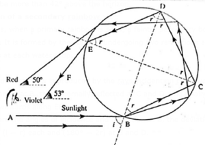
Formation of a secondary rainbow :
Sometimes, when a primary rainbow is seen, a fainter secondary bow is seen higher in the sky. It is formed by the sunrays undergoing two refractions and two internal reflections at each water drop, Fig.
The secondary rainbow is produced by the rays incident on the lower half of the drop, refracted at B, then internally reflected at C and D, and finally emerges into
the air downwards along EF.
If i and r are the angles of incidence and refraction at B, the deviation of the light at B and E is (i — r) each and (180° — 2r) at C and D.
Sometimes, when a primary rainbow is seen, a fainter secondary bow is seen higher in the sky. It is formed by the sunrays undergoing two refractions and two internal reflections at each water drop, Fig.
The secondary rainbow is produced by the rays incident on the lower half of the drop, refracted at B, then internally reflected at C and D, and finally emerges into the air downwards along EF.
If i and r are the angles of incidence and refraction at B, the deviation of the light at B and E is (i — r) each and (180° — 2r) at C and D.
For all the parallel rays entering the lower half of the drop, the total deviation, δ, in the anticlockwise sense is thus given by
δ = 2(i — r) + 2(180°—2r)
= 360° + 2i — 6r
The deviation is such that the observer, looking away from the Sun, sees the red colour in an arc subtending an angle of 50°34’ and the violet at an angle of 54° with the line joining the Sun to the observer. Therefore, the secondary or the outer bow is violet on the outside and red on the inside, in reverse order of the colours as compared with the primary bow.
Defects of lenses (aberrations of optical images):
Chromatic aberration : Chromatic aberration is a lens defect related to colour. Because different frequencies of light are refracted through different angles by the glass of the lens, violet light is deviated more than red light with the other colours somewhere in between. Hence, constituent colours of a collimated beam of white light are focused at different points. The resultant defect is known as chromatic aberration.
If the collimated beam is parallel to the principal axis, the axial distance between two focal points for extreme colours is called the axial or longitudinal chromatic
aberration (ACA).
ACA = fR — fV
Since violet light deviates the most, fV is closer to the lens than fR. For a positive lens (convex), ACA is positive; for a negative lens (concave), ACA is negative.
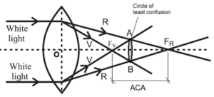
For a distant point object, a convex lens casts a real image surrounded by a circular halo. If the screen is moved nearer the lens, the image is blurred with a orange-red halo. Moving the screen away from the lens — beyond the best image — the image is again blurred but with a blue-violet halo. The position of the best image is the location of the circle of least confusion.
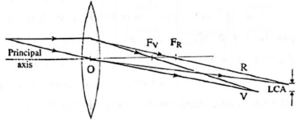
The image of an off-axis point for different colours will be formed at different distances from the principal axis. The vertical distance between two such points for extreme colours is called the lateral chromatic aberration (LCA).
Eliminating chromatic aberration :
Elimination of chromatic aberration for all colours is impossible. However, a combination of two thin lenses in contact, one convex and one concave and of two materials forming the lenses, can be used to eliminate the total dispersion for two specific colours. Such an arrangement is said to be achromatized for those two specific colours and is called an achromat.
Condition for achromatism : An achromatic combination aims to eliminate the total dispersion for two specific colours by using materials of different dispersive powers, ω1 and ω2 forming the lenses.
By the lens—makers’ formula,
\(\frac{1}{f}\) = (n—1)\(9\frac{1}{R_1}-\frac{1}{R_2})\) = (n—1)K
Abbreviating the notation for brevity, for the two lenses,
\(\frac{1}{f_1}\) = (n1 — 1)K1 and \(\frac{1}{f_2}\) = (n2 — 1)K2
For each lens of the combination, n and f vary with colour while K is constant. For two lenses in contact,
\(\frac{1}{f}=\frac{1}{f_1}+\frac{1}{f_2}\) = (n1 — 1)K1 + (n2 — 1)K2
= (n1K1 + n2K2) — (K1 + K2)
This expression will give the focal length of the achromatic doublet for red (fR) and violet (fV) when the appropriate refractive indices are used. For fR = fV,
\(\frac{1}{f_{1R}}+\frac{1}{f_{2R}}=\frac{1}{f_{1V}}+\frac{1}{f_{2V}}\)
∴ (n1RK1 + n2RK2) — (K1 + K2) = (n1VK1 + n2VK2) — (K1 + K2)
∴ (n1RK1 + n2RK2) = (n1VK1 + n2VK2)
∴ n1RK1 — n1VK1 = n2VK2 — n2RK2
∴ (n1R — n1V)K1 = (n2V — n2R)K2
∴ — (n1V — n1R)K1 = (n2V — n2R)K2
\(\frac{K_1}{K_2}=-\frac{n_{2V}-n_{2R}}{n_{1V}-n_{1R}}\) ……(1)
The focal length of the doublet can conveniently be specified as fY the focal length
for yellow light, which is roughly midway between the red and violet extremes.
\(\frac{1}{f_{1Y}}\) = (n1Y — 1)K1 and \(\frac{1}{f_{2Y}}\) = (n2Y — 1)K2
∴ \(\frac{f_{2Y}}{f_{1Y}}=\frac{n_{1Y}-1}{n_{2Y}-1}.\frac{K_1}{K_2}\) ……(2)
∴ \(\frac{f_{2Y}}{f_{1Y}}=\frac{n_{2V}-n_{2R}}{n_{2Y}-1}.\frac{n_{1Y}-1}{n_{1V}-n_{1R}}\) …..[from eq(1)]
= \(-\frac{ω_2}{ω_1}\) ……(3)
Equation (3) is the condition for achromatism.
Since dispersive powers are always positive, one lens of the achromatic doublet must be a positive or converging lens and the other a negative or diverging lens.
If the second lens is a concave lens, f2Y is negative.
∴ \(\frac{1}{f_Y}=\frac{1}{f_{1Y}}+\frac{1}{f_{2Y}}\)
For the combination to be converging, i.e., for fY > 0, f1Y < f2Y so that, from Eq.(3),
ω2 > ω1
Thus, in an achromat, the first lens is a convex lens of lower dispersive power than the second lens which is a concave lens.
Spherical aberration :
Longitudinal spherical aberration, transverse spherical aberration and circle of least confusion are defined in the same manner as that for spherical mirrors.
- Spherical aberration of a spherical lens is a focusing defect due to its spherical surfaces.
- A spherical lens forms reasonably sharp image if its aperture is small compared with its focal length and object and image distances. But if the aperture is large, the peripheral or abaxial rays refracted from the outer edges are brought to a focus closer to the optical centre than the paraxial rays, with varying focal lengths for rays in between. This focusing defect is called spherical aberration.
- It causes the image to look hazy due to lack of sharpness.
Figure shows rays incident parallel to the optical axis from a very distant on-axis point object.
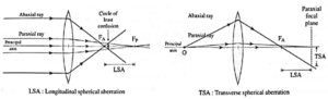
- On refraction, the paraxial rays meet at the paraxial focal point F2, while the abaxial rays fall short by a large amount.
- Rotating this diagram about the principal axis reveals a very blurry circular image in the paraxial plane.
- The least blurry image is produced a short distance to the left of the paraxial focal plane and is called the circle of least confusion.
- Figure shows how the spherical aberrations are quantitatively defined.
- The distance between the paraxial focal plane and the point where the ray crosses the principal axis is called the longitudinal spherical aberration (LSA). The distance of the ray from the principal axis at the pamxial focal plane is called the transverse spherical aberration (TSA).
Methods to reduce/eliminate spherical aberration of lenses:
- Cheapest method to reduce the spherical aberration is to use a planoconvex or planoconcave lens with curved side facing the incident rays (real object). Reversing it increases the aberration appreciably.
- Certain ratio of radii of curvature for a given refractive index almost eliminates the spherical aberration. For n = 5, the ratio is
\(\frac{R_1}{R_2}=\frac{1}{6}\) and for n = 2, it is
- Use of two thin converging lenses separated by distance equal to difference between their focal lengths with lens of larger focal length facing the incident rays considerably reduces spherical aberration.
- Spherical aberration of a convex lens is positive (for real image), while that of a concave lens is negative. Thus, a suitable combination of them (preferably a double convex lens of smaller focal length and a planoconcave lens of greater focal length) can completely eliminate spherical aberration.
Optical instruments:
Observed size of an object :An object appears small or big depending on the size of its image on the retina of the eye, This apparent size of an object as perceived by the eye is called its observed size.
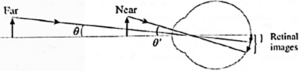
As an object is brought closer to the eye, accommodation permits the eye to increase its power and form a large retinal image. Also, the angle θ’ subtended by the object at the eye when it is closer is greater than the angle θ when it is more distant. This shows that the apparent size of an object depends on the angle subtended by the object at the eye.
Least distance of distinct vision :
- The human eye can normally focus objects from about 25 cm to infinity by changing the focal length of the crystalline lens.
- The short focal length of the lens required for near vision is produced by contraction of the ciliary muscles. Thus, to fix focus on an object held very close to the eye produces considerable strain on the ciliary muscles.
- The minimum distance at which the eye can focus without any strain is called the near point or the least distance of distinct vision.
- The least distance of distinct vision is taken to be 25 cm, approximating to that of the normal eye of a young adult.
- The near point recedes with age, from about 7 cm for a child 10 years old to about 200 cm for an adult 60 years old.
Simple magnifier or a simple microscope : A simple magnifier, also known as a simple microscope, is a single convex lens with a short focal length that is held in such a way that the item lies inside its focus length and a virtual, upright, and enlarged image of the object is generated at the near point of the eye.
How simple magnifier overcome the limitation of accommodation of the eye :
Explanation :
The eye is unable to accommodate sufficiently to form a sharp image if the object is closer than the near point of the eye.
When a convex lens is placed in between the object and the eye, the object can be brought much closer to the eye such that it lies within the focal length of the lens. The simple magnifier thus overcomes the limitation of the accommodation by forming a virtual image of a nearby object at a distance sufficiently far to permit comfortable viewing.
Magnifying power: The magnifying power of a microscope (simple and compound) is defined as the ratio of the visual angle subtended by the image at the eye to that subtended by the object held at the least distance of distinct vision and viewed directly.
Explanation :
If a small object is seen directly without any strain on the eye, it subtends the maximum visual angle at the eye when it is at the least distance of distinct vision. Let this angle of α, as shown in Fig. (a).
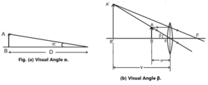
A simple microscope is a convex lens of short focal length placed between the object and the eye such that the object lies just within the focal length of the lens and the magnified virtual image is formed at the least distance of distinct vision.
The image subtends an angle β at the lens, Fig. (b). However, as the image is observed by keeping the eye close to the lens, β is also the angle subtended by the image at the eye.
The magnifying power (M) of a simple microscope is given by
M = β/α
Since the object being viewed is very small. the angles α and β are also small. With the angles measured in radian, we can use the small angle approximation. Therefore,
α ≈ tan α = BA/D ……[from fig (a)]
β = tan β = B’A’/v = BA/PB = BA/u ……[from fig (b)]
∴ M = \(\frac{β}{α}=(\frac{BA}{u})(\frac{D}{BA})=\frac{D}{u}\)
Maximum and minimum value in terms of focal length :
The focal length of a convex lens is given by
\(\frac{1}{f}=\frac{1}{v}-\frac{1}{u}\)
In this case, f is positive and u and v are both negative as per the Cartesian sign convention.
∴ \(\frac{1}{f}=-\frac{1}{v}-(-\frac{1}{u})\)
∴ \(\frac{1}{u}=\frac{1}{v}+\frac{1}{f}\)
∴ magnifying power, M = \(\frac{D}{u}=\frac{D}{v}+\frac{D}{f}\) ….(1)
Case (i) : For maximum magnifying power (Image is near point of the eye), the image should be nearest possible, i.e., at D.
When the image is formed at the least distance of distinct vision, v = D.
∴ M = \(\frac{D}{v}+\frac{D}{f}=\frac{D}{D}+\frac{D}{f}\) = \(1+\frac{D}{f}\) ….(2)
This is the maximum value of the magnifying power
Case (ii) : For minimum magnifying power (Image is far point of the eye), v = ∞ i.e., u = f (numerically)
∴ M = \(\frac{D}{v}+\frac{D}{f}=\frac{D}{∞}+\frac{D}{f}\) = \(\frac{D}{f}\) …..(3)
This is the minimum value of the magnifying power.
Lateral magnification :
The lateral magnification produced by a lens is the factor by which the image size is changed from the object size.
Lateral magnification, m = hi/ho = v/u
where ho = object height, hi = image height, u = object distance, and v =image distance.
If the object is positioned at the focal point of the lens (u = f), the virtual image is at ∞ (v = ∞).
Thus, m approaches infinity as u —> In marked contrast, the angular magnification or magnifying power of a single lens merely decreases by 1 under the same circumstances. Refer above equation (2) and (3)
| Remember : Because short focal length convex lenses are used as simple microscope, the magnifying powers for the above two extreme cases are approximately equal. Also, the image at the far point may be viewed more comfortably by a relaxed eye. Therefore, the simpler expression, D/f, is commonly used as the magnifying power of a simple microscope. |
Compound microscope:
- If higher magnifying power is needed, we go for using more than one lenses. The instrument is then called a compound microscope.
- A compound microscope consists of two converging lenses or lens systems mounted coaxially at the two ends of a metal tube.
- One of the lens systems, called the objective, has a short focal length, fo, and small aperture.
- The second converging lens system at a convenient distance, called the eyepiece or ocular, has a somewhat larger focal length, fo, and larger aperture.
Working :
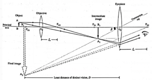
- The objective is adjusted so that the sample AB to be examined is just outside its focal length. The objective then forms a real, inverted, and magnified image, A1B1,
- By proper adjustment of the object distance, this image is formed just inside the focal length of the eyepiece.
- The image A1B1 now serves as the real object for the ocular. The ocular, performing the function of a simple magnifier, forms a virtual, highly magnified image A2B2 which is inverted relative to the object AB.
- In normal adjustment, the proper object distance is that for which this final image is formed at the near point of the eye.
Expressions for the magnifying power and length of a compound microscope using two convex lenses :
Derivation: Let at be the visual angle subtended by a small object AB when it is held at the near point of the eye and viewed directly.
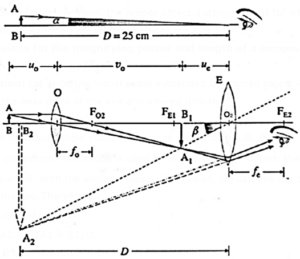
Let β be the visual angle subtended by the final image A2B2 Fig.
Since a compound microscope is used to view a very tiny object, the angles α and β are also small. With the angles measured in radian, we can use the small angle approximation.
Therefore,
α ≈ tan α = \(\frac{BA}{D}\) and
β ≈ tan β = \(\frac{B_2A_2}{O_2B_2}=\frac{B_1A_1}{O_2B_1}=\frac{B_1A_1}{u_e}\)
where D = least distance of distinct vision, and ue = distance of the intermediate image A1B1 from the eyepiece.
Let uo and vo be the object and image distances for the objective. The magnifying power M of the compound microscope is given by,
M = \(\frac{β}{α}= \frac{B_1A_1/u_e}{AB/D}=\frac{A_1B_1}{AB}×\frac{D}{u_e}\)
In this case, \(\frac{A_1B_1}{AB}=\frac{v_0}{u_0}\) = m0 = lateral magnification produced by the objective and
\(\frac{D}{u_e}\) = Me = magnifying power of the eyepiece.
∴ M = m0 x Me
Thus, the magnifying power of a compound microscope is equal to the product of
(i) the lateral magnification produced by the objective and
(ii) the magnifying power of the eyepiece, acting as a simple microscope.
Case (I) : Final image at the near point of the eye (Normal adjustment) :
Me = 1 + \(\frac{D}{f_e}\)
∴ M = m0 x Me = \(\frac{v_0}{u_0}(1+\frac{D}{f_e})\)
This is the maximum value of the magnifying power.
Case (II) : Final image at the far point of the eye :
Me = \(\frac{D}{f_e}\), ∴ M = m0 x Me = \(\frac{v_0}{u_0}×\frac{D}{f_e}\)
This is the minimum value of the magnifying power.
The length of a compound microscope = the distance between the objective and eyepiece = v0 + ue
Telescope:
- Telescopes are used to see terrestrial or astronomical bodies.
- A telescope essentially uses two lenses (or one large parabolic mirror and a lens). The lens facing the object (called objective) is of aperture as large as possible.
Terrestrial telescopes :
- A terrestrial telescope is one which is used for viewing distant objects on the Earth.
- For terrestrial telescopes the objects to be seen are on the Earth, like mountains, trees, players playing a match in a stadium, etc.
- In such case, the final image must be erect. Eye lens used for this purpose must be concave and such a telescope is popularly called a binocular.
- A variety of binoculars use three convex lenses with proper separation. The third lens again inverts the second intermediate image and makes final image erect with respect to the object.
Astronomical telescope :
- An astronomical retracting telescope consists of two converging lenses or lens systems mounted coaxially at the two ends of a metal tube.
- One of the lens systems, called the objective, has a large focal length, fo, and large aperture and is aimed at faint astronomical objects.
- The second converging lens system, called the eyepiece or ocular, has a much smaller focal length, fe, and smaller aperture.
Working :
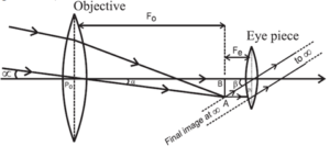
- Since the object distances are practically infinite, the objective forms a real, inverted and diminished image AB at the focal plane of the objective.
- Normally, the distance of the eyepiece from the objective is adjusted so that this image is located at the focal plane of the eyepiece.
- The eyepiece then produces a magnified, virtual image at infinity which is inverted relative to the object.
Magnifying power of a telescope: The magnifying power of a telescope is defined as the ratio of the visual angle subtended by the final image to that subtended by the object when viewed directly.
Derivation :
Since the object distance is practically infinite, the visual angle subtended by the object at the unaided eye, α is the same as that subtended by the parallel rays at the objective. A celestial object at an astronomical distance appears very small and so α is very small.

Also, the parallel rays from the object are brought to a focus at the focal plane of the
objective. Therefore, O1B1 = fo and, in the small angle approximation,
α ≈ tan α = \(\frac{B_1A_1}{O_1B_1}=\frac{B_1A_1}{f_o}\)
In the normal adjustment, O2B1 = fe the focal length of the eyepiece. The angle β subtended by the final image at the far point of the eye is very small and the same as that subtended by the intermediate image AIB1.
β ≈ tan β = \(\frac{B_1A_1}{O_2B_1}=\frac{B_1A_1}{f_e}\)
Therefore, the magnifying power of a telescope in normal adjustment is
M = \(\frac{β}{α}=\frac{B_1A_1}{f_e}×\frac{f_o}{B_1A_1}=\frac{f_o}{f_e}\)
Thus, the magnifying power of a telescope is equal to the ratio of the focal length of the objective to that of the eyepiece. Therefore, for greater magnifying power, the focal length of the objective must be large and that of the eyepiece small.
The length of an astronomical refracting telescope for normal adjustment = fo + fe.
Distinguish between a terrestrial telescope and an astronomical telescope :
| Terrestrial telescope | Astronomical telescope |
| A terrestrial telescope is one which is used for viewing distant objects on the Earth. | An astronomical telescope is used for viewing celestial objects like planets, stars and galaxies. |
| Terrestrial objects are not so dim
and hence a terrestrial telescope can be portable. |
Since an astronomical telescope is almost always aimed at a faint source, the objective must have a large light gathering power so that an astronomical telescope has to be built large. |
Distinguish between a microscope and telescope :
| Microscope | Telescope |
| In a compound microscope, the objective has a short focal length and a small aperture while the eyepiece has a larger focal length and larger aperture. | In a telescope, the objective has a large focal length and a large aperture while the eyepiece has a shorter focal length and a smaller aperture. |
| Function of the objective in a compound microscope : To form a real magnified image of high resolution which can then be further magnified by the eyepiece. | Function of the objective in a telescope : To form a real image of high resolution which can then be magnified by the eyepiece. The large aperture gathers as much of the light as possible because the distant object aimed at appears very faint. |
| Functions of the eyepiece in a compound microscope : To act as a simple magnifier and form a highly magnified image at the least distance of distinct vision (the near point of the eye). Its larger aperture permits most of the light rays admitted by the small aperture of the objective. | Function of the eyepiece in a telescope : To act as a simple magnifier and form a highly magnified image at infinity (the far point of the eye). |
| The normal adjustment of a compound
microscope is such that the final image is formed at the least distance of distinct vision (the near point of the eye) |
The normal adjustment for a
telescope is at infinity (the far point of the eye). |
| To focus a compound microscope, the distance of the object from the objective is adjusted. | Since an object observed through a telescope is practically at infinite distance, the distance between the objective and the eyepiece lenses is adjusted to focus a telescope. |
We reply to valid query.