Notes-Part-2
Topics to be Learn : Part-2
|
Interference:
| Let’s recall :
Principle of superposition of waves :The displacement at a point due to the combined effect of a number of waves arriving simultaneously at the point is the vector sum of the displacements due to the individual waves arriving at the point. Explanation :This is a general principle of linear systems applied to wave phenomena. When two or more wave trains arrive at a point simultaneously, they interpenetrate without disturbing each other. The resultant displacement at that point is the vector sum of the displacements due to the individual waves arriving at the point. The amplitude and phase angle of the resulting disturbance are functions of the individual amplitudes and phases. |
Interference of light : The phenomenon in which the superposition of two or more light waves produces a resultant disturbance of redistributed light intensity or energy is called the interference of light.
- Light waves are transverse in nature. If two monochromatic light waves of the same frequency arrive in phase at a point, the crest of one wave coincides with the crest of the other and the trough of one wave coincides with the trough of the other. Therefore, the resultant amplitude and hence the resultant intensity of light at that point is maximum and the point is bright. This phenomenon is called constructive interference.
- If two light waves having the same amplitude are in opposite phase, the crest of one wave coincides with the trough of the other. Therefore, the resultant amplitude, and hence the intensity, at that point is minimum (zero) and the point is dark. This phenomenon is called destructive interference.
- If the amplitudes are unequal, the resultant amplitude is minimum, but not zero. At other points, the intensity of light lies between the maximum and zero.
Demonstration of phenomenon of interference :
Construction : Two pins, a small distance d apart, are attached to the electrical vibrator or an electrically maintained tuning fork of a ripple tank. The pins are kept vertical with their tips in contact with the surface of water in the ripple tank.
When the vibrator is switched on, the two pins vibrate together in phase with the same frequency and the same amplitude. Their tips form the sources S1 and S2 of circular waves which spread outward along the water surface.
Phenomenon of interference : Along some straight lines radially diverging from the midpoint of S1S2, there is constructive (along the radial lines connecting the blue dots) and destructive (along the radial lines connecting the red dots) interference. Click here to View Figure-1
The waves from the two sources interfere constructively at points where they meet in phase. Thus, where the crest of a wave from S1 is superposed on the crest of a wave from S2 (such as point P), and where the trough of a wave from S1 is superposed on the trough of a wave from S2 (such as point Q), the water molecules have maximum amplitude of vibration. The waves from the two sources interfere destructively at points where the meet in opposite phase. Thus, where the crest of wave from S1 is superposed on the trough of a wave from S2 (such as point R), and where the trough of a wave from S1 is superposed on the crest of a wave from S2 (such as point S), the water molecules have minimum amplitude of vibration.

Coherent Sources of Light:
Two sources which emit waves of the same frequency having a constant phase difference, independent of time, are called coherent sources.
Why it is not possible to observe interference pattern with light from any two different sources :
- This is because, no observable interference phenomenon occurs by superposing light from two different sources.
- This happens due to the fact that different sources emit waves of different frequencies.
- Even if the two sources emit light of the same frequency, the phase difference between the wave trains from them fluctuates randomly and rapidly, i.e., they are not coherent.
- Consequently, the interference pattern will change randomly and rapidly, and steady interference pattern would not be observed.
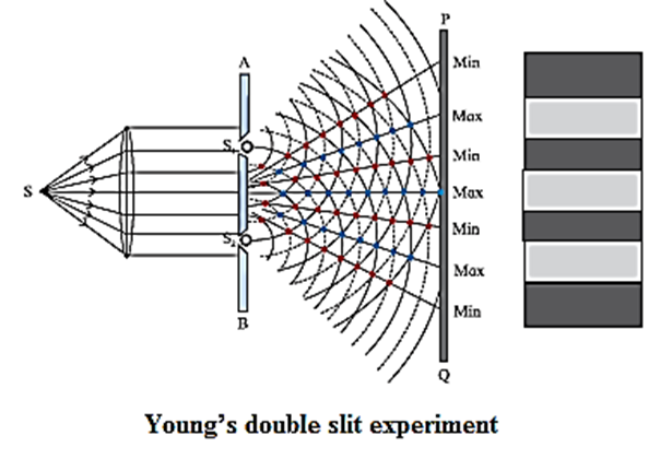
Young’s Double Slit Experiment:
In this experiment, a plane wavefront is made to fall on an opaque screen AB having two similar narrow slits S1 and S2.
- A plane wavefront is obtained by placing a linear source S of monochromatic light at the focus of a convex lens.
- It is then made to pass through an opaque screen AB having two narrow and similar slits S1 and S2.
- S1 and S2 are equidistant from S so that the wavefronts starting simultaneously from S and reaching S1 and S2 at the same time are in phase.
- A screen PQ is placed at some distance from screen AB as shown in Fig.
Click here to View Figure-2

- S1 and S2 act as secondary sources. The crests/troughs of the secondary wavelets superpose and interfere constructively along straight lines joining the black dots shown in Fig. The point where these lines meet the screen have high intensity and are bright.
- Similarly, there are points shown with red dots where the crest of one wave coincides with the trough of the other. The corresponding points on the screen are dark due to destructive interference.
- These dark and bright regions are called fringes or bands and the whole pattern is called interference pattern.
Conditions for occurrence of dark and bright fringes on the screen : (Consider Young's double—slit experimental set up.) Two narrow coherent light sources are obtained by wavefront splitting as monochromatic light of wavelength A emerges out of two narrow and closely spaced, parallel slits S1 and S2 of equal widths. The separation S1S2 = d is very small. The interference pattern is observed on a screen placed parallel to the plane of S1S2 and at considerable distance D (D >> d) from the slits. OO’ is the perpendicular bisector of segment S1S2, Fig. Click here to View Figure-3
Consider, a point P on the screen at a distance y from O’ (y << D). The two light waves from S1 and S2 reach P along paths S1P and S2P, respectively. If the path difference (Δl) between S1P and SZP is an integral multiple of λ, the two waves arriving there will interfere constructively producing a bright fringe at P. On the contrary, if the path difference between S1P and S2P is half integral multiple of λ, there will be destructive interference and a dark fringe will be produced at P. From above Fig. (S2P)2 = (S2S2’)2 + (PS2’)2 = (S2S2’)2 + (PO’ + O’ S2’)2 = D2 + \((y+\frac{d}{2})^2\) ……. (1) and (S1P)2 =(S1S1’)2 + (PS1’)2 =(S1S1’)2 + (PO’—O’ S1’)2 = D2 + \((y-\frac{d}{2})^2\) …… (2) (S2P)2 − (S1P)2 = \([D^2 + (y-\frac{d}{2})^2]\) – \([D^2 +(y-\frac{d}{2})^2]\) ∴ (S2P + S1P)(S2P − S1P) = [D2 + y2 + \(\frac{d^2}{2}\) + yd] – [D2 + y2 + \(\frac{d^2}{2}\) – yd] = 2yd ∴ S2P − S1P = Δl = 2yd/(S2P + S1P) In practice, D >> y and D >> d S2P + S1P ≈ 2D Path difference, Δl = (S2P − S1P) ≈ \(2\frac{yd}{2D} = y\frac{d}{D}\) ….. (3)

Expression for the fringe width (or band width) ; The distance between consecutive bright (or dark) fringes is called the fringe width (or band width) W, Point P will be bright (maximum intensity), if the path difference, Δl = yn \(\frac{d}{D}\) = n λ where n = 0, 1, 2, 3..., Point P will be dark (minimum intensity equal to zero), if ym \(\frac{d}{D}\) = (2m — 1)\(\frac{λ}{2}\) , where, m = 1, 2, 3..., Thus, for bright fringes (or bands), yn = 0, \(\frac{λD}{d}\) , \(\frac{2λD}{d}\) …. and for dark fringes (or bands), ym = \(\frac{λD}{2d}\) , \(\frac{3λD}{2d}\), \(\frac{5λD}{2d}\) …. These conditions show that the bright and dark fringes (or bands) occur alternately and are equally spaced. For Point O’, the path difference (S2O’ — S1O’) = 0. Hence, point O’ will be bright. It corresponds to the centre of the central bright fringe (or band). On both sides of O’, the interference pattern consists of alternate dark and bright fringes (or band) parallel to the slit. Let yn and yn +1, be the distances of the nth and (n + 1)th bright fringes from the central bright fringe. . ∴ yn \(\frac{d}{D}\) = n λ , ∴ yn = \(\frac{nλD}{d}\) ….. (4) And \(\frac{y_{n+1}d}{D}\) = (n+1)λ, ∴ yn+1 = \(\frac{(n+1)λD}{d}\) ….. (5) The distance between consecutive bright fringes = yn+1 − yn = \(\frac{λD}{d}[(n+1)-n]\) = \(\frac{λD}{d}\) …….(6) Hence, the fringe width, ∴ W = Δy = yn+1 − yn = \(\frac{λD}{d}\) (fo rbright fringes) ...(7) Alternately, let ym and ym +1 be the distances of the m th and (m + 1)th dark fringes respectively from the central bright fringe. ∴ \(\frac{y_md}{D}\) = (2m—1)\(\frac{λ}{2}\) and \(\frac{y_{m+1}d}{D}\)= [2(m+1)—1]\(\frac{λ}{2}\) = (2m+1)\(\frac{λ}{2}\) …. (8) ∴ ym = (2m—1) \(\frac{λD}{2d}\) and ym +1 = (2m+1)\(\frac{λD}{2d}\) The distance between consecutive dark fringes, ym+1—ym = \(\frac{λD}{2d}\)[(2m+1)-(2m-1)] = \(\frac{λD}{d}\)...(10) ∴ W = ym+1 − ym = \(\frac{λD}{d}\)(for dark fringes) …..(11) Eqs. (7) and (11) show that the fringe width is the same for bright and dark fringes. [Note: In the first approximation, the path difference is d sin θ. See Fig-3.]
Q. Derive conditions for occurrence of dark and bright fringes on the screen in terms of phase difference.
Please Ref- (Conditions for occurrence of dark and bright fringes on the screen) The distance between consecutive bright (or dark) fringes is called the fringe width (or band width) W, Point P will be bright (maximum intensity), if the path difference, Δl = yn \(\frac{d}{D}\) = n λ where n = 0, 1, 2, 3..., Point P will be dark (minimum intensity equal to zero), if ym \(\frac{d}{D}\) = (2m — 1)\(\frac{λ}{2}\) , where, m = 1, 2, 3..., The relation between path difference (Δl) and phase difference ΔΦ is ΔΦ = \(\frac{2π}{λ}\) Δl ……(4) Thus, the phase difference between the two waves reaching P, from S1 and S2 is ΔΦ = \(y\frac{d}{D}\frac{2π}{λ}\) ...(5) The condition for constructive interference in terms of the phase difference is ΔΦn = 2nπ, n = 0, ±1, ±2 …. The path difference between the two waves reaching P is, Δl = \(\frac{λ}{2π}\) ΔΦn = \(\frac{λ}{2π}\)(2nπ) = nλ ∴ Δl = nλ Hence, the condition for constructive interference at a point is that, two waves reaching the point should have a phase difference of zero or an even integral multiple of 2π. Similarly, the path difference between two waves reaching the point should be zero or an integral multiple of wavelength. The condition for destructive interference in terms of phase difference is ΔΦm = (2m-1)π or ΔΦm = π, 3π, 5π ……(8) where, m = ±1, ±2 …… The path difference between the two waves is, Δl = \(\frac{λ}{2π}\)ΔΦm = \(\frac{λ}{2π}\)(2m-1)π = (2m-1)\(\frac{λ}{2}\) ……(9) Hence, the condition for destructive interference at a point is that the phase difference between the two waves reaching the point should be an odd integral multiple of p or the path difference between the two waves reaching the point should be an odd integral multiple of half the wavelength.
Importance of Young's experiment to Observe the interference of light :
- It was the first experiment (1800-04) in which the interference of light was observed.
- This experiment showed that light is propagated in the form of waves.
- From this experiment, the wavelength of monochromatic light can be determined.
Nature of the interference pattern obtained using white light :
| Remember :
For the interference pattern to be clearly visible on the screen, the distance (D) between the slits and the screen should be much larger than the distance (d) between two slits, i.e., D>>d. Already used this condition while deriving Eq. Δl = yn \(\frac{d}{D}\) = n λ ….(1) yn being the position (y-coordinate) of nth bright fringe (n = 0, ±1, ±2, …). It is given by yn= n λ D/d …..(2) Similarly, the position of mth (m = ±1, ±2,..) dark fringe (destructive interference) is given by, Δl = ym \(\frac{d}{D}\) = (2m-1)λ giving ym = (2m—1)λ\(\frac{d}{D}\) …. (3) The distance between any two consecutive bright or dark fringes, i.e., the fringe width W = Δy = yn+1 − yn = λ\(\frac{d}{D}\) ….(4) Conditions given by Eqs. (1) to (4) and hence the location of the fringes are derived assuming that the two sources S1 and S2 are in phase. If there is a non- zero phase difference between them it should be added appropriately. This will shift the entire fringe pattern but will not change the fringe width. |
Q. What happens to the interference pattern when the phase difference between the two sources of light changes with time ?
Ans. If the two sources do not maintain their phase relation during the time required for observation, the intensity of light at any point on the screen and consequently the interference pattern changes rapidly, and hence steady interference pattern is not observed.
Intensity distribution:
Obtaining expressions in terms of electric field, for the resultant amplitude and the intensity for the interference pattern produced by monochromatic light waves from two coherent sources :
Consider a two-source interference pattern produced by superposition of monochromatic light waves of angular frequency w, wavelength λ and constant phase difference, Φ. At the centre of a bright fringe, there is constructive interference.
Here, the amplitude of the resultant wave is double the amplitude of the wave incident on AB. Now, the intensity is proportional to the square of the amplitude of the wave. Hence, the resultant intensity is, I = 4I0, where Io is the intensity of the incident wave.
At the centre of a dark fringe, there is destructive interference. Here, the amplitude of the resultant wave and hence the intensity is zero. At other points the intensity is between 4I0 and zero, depending on the phase difference.
Click here to View Figure-4
Let the equations of the two waves coming from S1 and S2 at some point in the interference pattern be, E1 = E0 sin ωt and E2 =E0 sin (ωt+Φ) respectively, where E0 is the amplitude of the electric field vector.
By the principle of superposition of waves, the resultant electric field at that point is the algebraic sum, E = E1 + E 2
E = E0 sin ωt + E0 sin (ωt + Φ )
= E0 [sin ωt + sin (ωt + Φ)]
= 2 E0 sin (ωt + Φ/2) cos (Φ/2)
The amplitude of the resultant wave is
2E0 cos (Φ/2).
Therefore, the intensity at that point is
I ∝ |2 E0 cos (Φ/2)|2
∴ I = 4I0 cos2 (Φ/2)
as I0 ∝ |E0|2
Q. Monochromatic light waves of amplitudes E10 and E20 and a constant phase difference Φ produce an interference pattern. State an expression for the resultant amplitude at a point in the pattern. Hence, deduce the conditions for
(i) constructive interference with maximum intensity
(ii) destructive interference with minimum intensity.
(iii) Show that the ratio of the maximum and minimum intensities is
\(\frac{I_{max}}{I_{min}}=(\frac{E_{10}+E_{20}}{E_{10}-E_{20}})^2\)
Consider a two-source interference pattern produced by monochromatic light waves of angular frequency co, wavelength Z, amplitudes E10 and E20 and a constant phase difference Φ. Let the individual electric fields along the same line due to the waves at some point in the interference pattern be E1 = E10 sin ωt and E2 = E20 sin (ωt + Φ ) By the principle of superposition of waves, the resultant electric field (displacement) at that point is the algebraic sum E = E1 + E2 = E10 sin ωt + E20 sin (ωt + Φ ) E10 sin ωt + E20 sin ωt cos Φ + E20 cos ωt sin Φ = (E10 + E20 cos Φ) sin ωt + E20 sin Φ cos ωt Let E10 + E20 cos Φ = R cos θ and E20 sin Φ =R sin θ ∴ E = R cos θ sin ωt+R sin θ cos ωt = R(sin ωt cos θ + cos ωt sin θ) =R sin (ωt + θ) The resultant amplitude is, |R| = \(\sqrt{E_{10}^2+E_{20}^2 +E_{10}E_{20}cos\,Φ}\) ...(1) Since, the intensity of a wave is proportional to the square of its amplitude, the resultant intensity at P, I ∝ |R|2 I ∝ E102 + E202 + 2E10 E20 cos Φ ….. (2) Thus, the intensity depends on cos Φ. The condition for constructive interference with maximum intensity is cos Φ is maximum, equal to 1, i.e., Φ = 2np (n = 0, 1, 2, 3...) ……(3) The condition for destructive interference with minimum intensity is cos Φ is minimum equal to — 1, i.e., Φ = (2m-1)p (m = 1, 2, 3...) ….(4) At points where R and I are maximum Rmax = E10 + E20 …..(5) and Imax ∝ E102 + E202 + 2E10 E20 ∴ Imax ∝ (E10+E20)2 ….(6) At points where R and I are minimum, Rmin = |E10 − E20| ….(7) and Imin ∝ E102 + E202 − 2E10 E20 ∴Imin ∝ (E10 − E20)2 ….(8) From Eqs. (6) and (8), \(\frac{I_{max}}{I_{min}}=(\frac{E_{10}+E_{20}}{E_{10}-E_{20}})^2\) ……(9) \(\frac{I_{max}}{I_{min}}=(\frac{E_{10}+E_{20}}{E_{10}-E_{20}})^2\) =\((\frac{1+r}{1-r})^2\) where r is E20/E10
We can write above equation as
Conditions for Obtaining Well Defined and Steady Interference Pattern: The following conditions have to be satisfied for the interference pattern to be steady and clearly visible. (1) The two sources of light should be coherent. (2) The two sources of light must be monochromatic : (3) The two interfering waves must have the same amplitude : (4) The separation between the two light sources must be small in comparison to the distance between the plane containing the slits and the observing screen: (5) The two light sources should be narrow : (6) The interfering light waves should be in the Same state of polarization :
| Interference due to thin film :
Several phenomena that we come across in our day to day life are caused by interference and diffraction of light. These are the vigorous colours of soap bubbles as well as those seen in a thin oil film on the surface of water, the bright colours of butterflies and peacocks etc. Most of these colours are not due to pigments which absorb specific colours but are due to interference of light waves that are reflected by different layers. Interference due to thin films: Click here to View Figure-5
The brilliant colours of soap bubbles and thin oil films on the surface of water are due to the interference of light waves reflected from the upper and lower surfaces of the film. The two rays have a path difference which depends on the point on the film that is being viewed. This is shown in the figure.
As the reflection is from the denser boundary, there is an additional phase difference of p radians (or an additional path difference λ ). This should be taken into account for mathematical analysis. |

Methods for Obtaining Coherent Sources:
In Young’s double slit experiment, we obtained two coherent sources by making the light from a single source pass through two narrow slits. There are other ways to get two coherent sources.
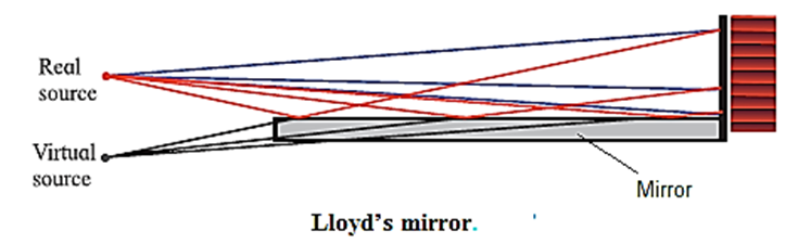
In the laboratory, coherent sources can be obtained by 'using (1) Lloyd's mirror and (2) Fresnel's bi-prism.
Lloyd's mirror : A plane polished mirror is kept at some distance from the source of monochromatic light and light is made incident on the mirror at a grazing angle. Click here to View Figure-6
Fresnel’s Biprism : It is a single prism having an obtuse angle of about 178° and the other two angles of about 1° each. The biprism can be considered as made of two thin prisms of very small retracting angle of about 1°. Click here to View Figure-7

Optical Path:
Optical path length : Consider, a light wave of angular frequency ω and wave vector k travelling through vacuum along the x-direction. The phase of this wave is (kx—ωt) The speed of light in vacuum is c and that in medium is v
k = \(\frac{2π}{λ}=\frac{2πν}{νλ}=\frac{ω}{v} \) as ω = 2πν and v = νλ, where ν is the frequency of light.
If the wave travels a distance Δx, its phase, changes by ΔΦ = kΔx = ωΔx/v.
Similarly, if the wave is travelling in vacuum,
K = ω/c and ΔΦ = ωΔx/c
Now, consider a wave travelling a distance Δx in the medium, the phase difference generated is,
ΔΦ’=k'Δx = ωnΔx/c = ωΔx’/c …...(1)
where Δx’ = nΔx ... (2)
The distance nΔx is called the optical path length of the light in the medium; it is the distance the light would have travelled in the same time t in vacuum (with the speed c).
The optical path length in a medium is the corresponding path in vacuum that the light travels in the same time as it takes in the given medium.
Now, speed = distance/time
∴ time = distance/speed
∴ t = dmedium/vmedium = dvaccum/vvaccum
Hence the optical path = dvaccum = \(\frac{v_{vaccum}}{v_{mediuam}}×d_{medium}\) = n x dmedium
Thus, a distance d travelled in a medium of refractive index n introduces a path difference = nd — d = d(n — 1) over a ray travelling equal distance through vacuum.
Two waves interfere constructively when their optical path lengths are equal or differ by integral multiples of the wavelength.
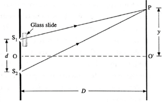
Expression for the positions of the bright fringes and interference pattern, if we introduce a transparent plate (glass slide) of thickness t and refractive index n in front of slit S1
Derivation of expression : Click here to View Figure-8
If the experiment is set up in free space, this introduces an additional optical path length (ng — 1)b in the path S1P. Then, the optical path difference to the point P from S1 and S2 is, Δl = S2P—[S1P+(ng— 1)b] =(S2P − S1P) − (ng_1)b = y\(\frac{d}{D}\) − (ng − 1)b ……..(1) where y = PO’, d is the distance between S1 and S2, and D is the distance of the screen from S1 and S2. Thus, point P will be bright (maximum intensity) if Δl = n λ where n =0, 1, 2, . The central bright fringe corresponding to n = 0, will be obtained at a distance yo from O’ such that, Δl = yo \(\frac{d}{D}\) − (ng − 1)b = 0 ∴ yo \(\frac{d}{D}\) = (ng − 1)b ∴ yo = \(\frac{D}{d}\)(ng − 1)b ...(2) Therefore, the central bright fringe and the interference pattern will shift up (towards P) by a distance yo given by Eq. (2). The distance of the nth bright fringe from O’ towards P is, yo \(\frac{d}{D}\)− (ng − 1)b = nλ ∴ yo = \(\frac{D}{d}\)[nλ +(ng—1)b] ……(3) The distance of the (n + 1)th bright fringe from O’ towards P is yn=1 = \(\frac{D}{d}\)[(n+1)λ +(ng—1)b] …. (4) Therefore, the fringe width, W = yn=1 — yo = \(\frac{λD}{d}\) …..(5) Thus, the fringe width remains unchanged
Diffraction of Light:
Phenomenon of diffraction of light : When light passes by the edge of an obstacle or through a small opening or a narrow slit and falls on a screen, the principle of rectilinear propagation of light from geometrical optics predicts a sharp shadow. However, it is found that some of the light deviates from its rectilinear path and penetrates into the region of the geometrical shadow. This is a general characteristic of wave phenomena, which occurs whenever a portion of the wavefront is obstructed in some way. This bending of light waves at an edge into the region of geometrical shadow is called diffraction of light.
Differences between interference and diffraction :
- The term interference is used to characterise the superposition of a few coherent waves (say two) But when the superposition at a Point involves a large number of waves coming from different parts of the same wavefront, the effect is referred to as diffraction.
- Double-slit interference fringes are all of equal width. In single-slit diffraction pattern, only the non-central maxima are of equal width which is half of that of the central maximum.
- In double-slit interference, the bright and dark fringes are equally spaced. In diffraction, only the non-central maxima lie approximately halfway between the minima.
- In double-slit interference, bright fringes are of equal intensity. In diffraction, successive non-central maxima decrease rapidly in intensity.
[Note : Interference and diffraction both have their origin in the principle of superposition of waves. There is no physical difference between them. It is just a question of usage. When there are only a few sources, say two, the phenomenon is usually called interference. But, if there is a large number of sources the word diffraction is used.]
Diffraction can be classified into two types depending on the distances involved in the experimental setup :
- Fraunhofer diffraction : In this class of diffraction, both the source and the screen are at infinite distances from the aperture. This is achieved by placing the source at the focus of a convex lens and the screen at the focal plane of another convex lens.
- Fresnel diffraction: In this case, the distances are much smaller and the incident wavefront is either cylindrical or spherical depending on the source. A lens is not required to observe the diffraction pattern on the screen.
Click here to View Figure-9

Fraunhofer diffraction pattern due to a single slit :
When a parallel beam of monochromatic light of wavelength λ illuminates a single slit of finite width a, we observe on a screen some distance from the slit, a broad pattern of alternate dark and bright fringes. The pattern consists of a central bright fringe, with successive dark and bright fringes of diminishing intensity on both sides. This is called the diffraction pattern of a single slit.
Consider a single slit illuminated with a parallel beam of monochromatic light perpendicular to the plane of the slit. The diffraction pattern is obtained on a screen at a distance D ( >> a) from the slit and at the focal plane of the convex lens, see Fig.
Location of minima and maxima: We can imagine the single slit as being made up of a large number of Huygens’ sources evenly distributed over the width of the slit. Then the maxima and minima of the pattern arise from the interference of the various Huygens’ wavelets
Click here to View Figure-10
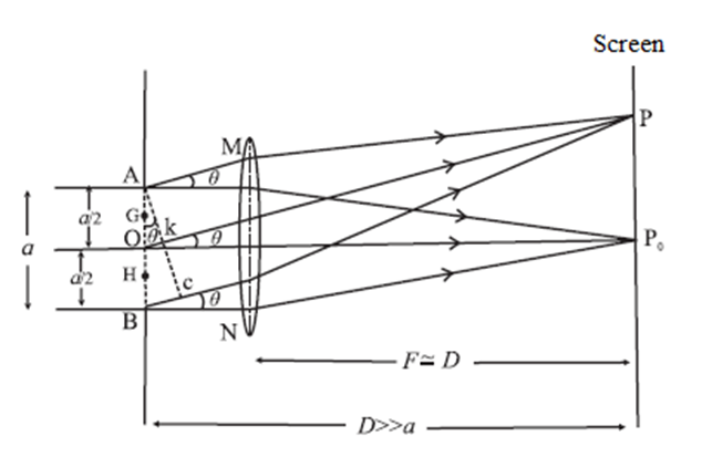
Now, imagine the single slit as made up of two adjacent slits, each of width a/2. Since, the incident plane wavefronts are parallel to the plane of the slit, all the Huygens sources at the slit will be in phase.
They will therefore also in phase at the point P0 on the screen, where P0 is equidistant from all the Huygens sources. At P0, then, we get the central maximum.
Expressions for the positions of the intensity minima and maxima : For the first minimum of intensity on the screen, the path difference between the waves from the Huygens sources A and O (or O and B) is λ/2, which is the condition for destructive interference. Suppose, the nodal line OP for the first minimum subtends an angle θ at the slit; θ is very small. With P as the centre and PA as radius, strike an arc intersecting PB at C. Since, D >> a, the arc AC can be considered a straight line at right angles to PB. Then, Δ ABC is a right-angled triangle similar to Δ OP0P. This means that, ∠ BAC = 0 ∴ BC = a sin θ Difference in path length, ∴ BC = PB − PA = (PB—PO) + (PO—PA) = \(\frac{λ}{2}+\frac{λ}{2}\) = λ ∴ a sin θ = λ ∴ sin θ ≈ θ = λ/a …....(1) ….('.' θ is very small and in radian) The other nodal lines of intensity minima can be understood in a similar way. In general, then, for the mth minimum (m = ±1, ±2, ±3, ...). θm = mλ/a ...(mth minimum) …..(2) as θm is very small and in radian. Between the successive minima, the intensity rises to secondary maxima when the path difference is an odd-integral multiple of λ/2 a sin θm = (2m+1)\(\frac{λ}{2}\) = (m+\(\frac{1}{2}\) ) λ i.e., at angles given by, θm ≈ sin θm = (m+\(\frac{1}{2}\))\(\frac{λ}{a}\) (mth secondary maximum) (3) Width of the central maximum : Equation (1) gives the angular half width of the central maximum. Therefore, the angular width of the central maximum is, 2θ = 2λ/a …..(4) From Δ OP0P, P0P = D tan θ ≈ D sin θ ('.' θ is very small and in radian) ∴ y1 = P0P = Dλ/a [from Eq. (1)] …..(5) This is the distance of the first minimum from the centre of the central maximum. ∴ Width of the central bright fringe : Wc = 2y1d = 2W = 2\(\frac{λD}{a}\) ...(6) The central bright fringe is spread between the first dark fringes on either side. Thus, the width of the central bright fringe is the distance between the centres of the first dark fringe on either side. If the lens is very close to the slit, D is very nearly equal to f, where f is the focal length of the lens. Then Wc = 2\(\frac{λD}{a}\) = 2\(\frac{λf}{a}\)
Expressions for the distances of minima and maxima from the central bright point for the diffraction by a single slit : Refer to the up to Eq. (3) and continue… Equations (2) and (3) relate the path difference at the locations of the mth dark and the mth bright point respectively. As the distance D >> a, the angle θ is very small. θ is expressed in radian. , ∴ sin θ ≈ tan θ ≈ θ = y/D where y is the distance of point P on the screen from the central bright point. Let ymd and ymb be the distances of the mth dark point and the mth bright point from the central bright point. At the mth dark point on either side of the central bright point. θmd = \(\frac{y_{md}}{D}\) = m\(\frac{λ}{a}\) ..[by Eq. (2)] ∴ ymd = m\(\frac{λD}{a}\) = mW …..(4) At the mth bright point on either side of the central bright point, θmb ≈ \(\frac{y_{mb}}{D}\) ≈ \((m+\frac{1}{2})\frac{λ}{a}\) ..[by Eq. (3)] ∴ ymb ≈ \((m+\frac{1}{2})\frac{λD}{a}\) ≈ \((m+\frac{1}{2})W\) …..(5) W = \(\frac{λD}{a}\) is similar to the fringe width 1n consecutive bright or consecutive dark fringes, except the central (zeroth) bright fringe.
| Know this :
Why did we use λ as the path difference between the waves originating from extreme points for the first minima?
|
Comparison of Young’s Double Slit Interference Pattern and Single Slit Diffraction Pattern: For nth dark fringe
Physical Quantity
Young’s double slit interference Pattern
Single slit diffraction pattern
Fringe width W
W = \(\frac{λD}{d}\)
W = \(\frac{λD}{a}\) Except for the central bright fringe
For nth bright fringe
Phase difference, Φ between extreme rays
n(2π)
\((n+\frac{1}{2})\)(2π)
Angular position, θ
\(\frac{nλ}{d}\)
\((n+\frac{1}{2})\frac{nλ}{d}\)
Path difference, ∆l between extreme rays
n λ
\((n+\frac{1}{2})\)λ
Distance from the central bright spot, y
n\(\frac{λD}{d}\)= nW
\((n+\frac{1}{2})\frac{λD}{a}\)= nW
Phase difference, Φ between extreme rays
\((n-\frac{1}{2})\)(2π)
n(2π)
Angular position, θ
\((n-\frac{1}{2})\frac{nλ}{d}\)
\(\frac{nλ}{d}\)
Path difference, ∆l between extreme rays
\((n-\frac{1}{2})\)λ
n λ
Distance from the central bright spot, y
\((n-\frac{1}{2})\frac{λD}{a}\)= nW
n\(\frac{λD}{d}\)= nW
Graphical representation of Intensity (I) distribution in
(a) Young’s double slit interference
(b) single slit diffraction and
(c) double slit diffraction.
Click here to View Figure-11

Characteristics of a single-slit diffraction pattern :
Double-slit diffraction pattern :
The double-slit diffraction pattern is determined by the diffraction patterns due to the individual slits, and by the interference between them. (see Fig.)
Click here to View Figure-12
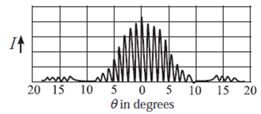
There are narrow interference fringes similar to those in Young’s double slit experiment, but of varying brightness and the shape of their envelope is that of the single slit diffraction pattern.
Q. What should be the order of the size of an obstacle or aperture to produce diffraction of light?
Ans. For pronounced diffraction, the size of an obstacle or aperture should be of the order of the wavelength of light or greater.
Resolving Power:
Resolving power of an optical instrument:
Ability to distinguish two physically separated objects as two distinct objects is known as the resolving power of an optical instrument.
Explanation : The primary aim of using an optical instrument is to see fine details, whether observing a star system through a telescope or a living cell through a microscope. After passing through an optical system, light from two adjacent parts of the object should produce sharp, distinct (separate) images of those parts. The resolving power of an optical instrument, e.g., a telescope or microscope, is a measure of its ability to produce detectably separate images of objects that are close together. Therefore, the smallest linear or angular separation between two point objects which appear just resolved when viewed through an optical instrument is called the limit of resolution of the instrument and its reciprocal is called the resolving power of the instrument.
Rayleigh’s Criterion for Limit of Resolution (or for Resolving Power):
Two overlapping diffraction patterns due to two point sources are acceptably or just resolved if the centre of the central peak of one diffraction pattern is as far as the first minimum of the other pattern.
The ‘sharpness’ of the central maximum of a diffraction pattern is measured by the angular separation between the centre of the peak and the first minimum. It gives the limit of resolution.
Click here to View Figure-13
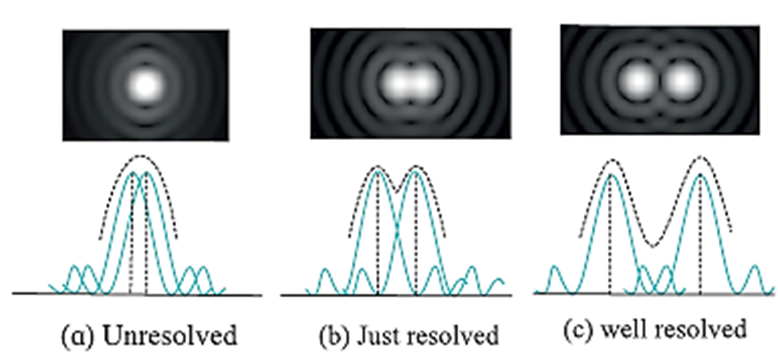
- Two overlapping diffraction patterns due to two point sources are not resolved if the angular separation between the central peaks is less than the limit of resolution [above Fig (a)].
- They are said to be just separate, or resolved, if the angular separation between the central peaks is equal to the limit of resolution [Fig.(b)].
- They are said to be well resolved if the angular separation between the central peaks is more than the limit of resolution [Fig. (c)].
Rayleigh criterion for the limit of resolution for (i) two linear objects (ii) a pair of point objects.
(i) Two linear objects : Consider, two self luminous objects or slits separated by some distance Let λ be the wavelength of the light and a the width of the slits. As per the Rayleigh criterion, the first minimum of the diffraction pattern of one of the sources should coincide with the central maximum of the other. Thus, it is at the just resolved condition. The angular separation dθ (position) of the first principal minimum is, dθ = λ/a This angular separation between the two objects must be minimum as this minimum coincides with the central maximum of the other. This is called the limit of resolution of that instrument. It is written as’ limit of resolution, dθ = λ/a Minimum separation between the two linear objects that are just resolved, at distance D from the instrument is, Y = D(dθ) = Dλ/a ...(2) It is the distance of the first minimum from the centre.
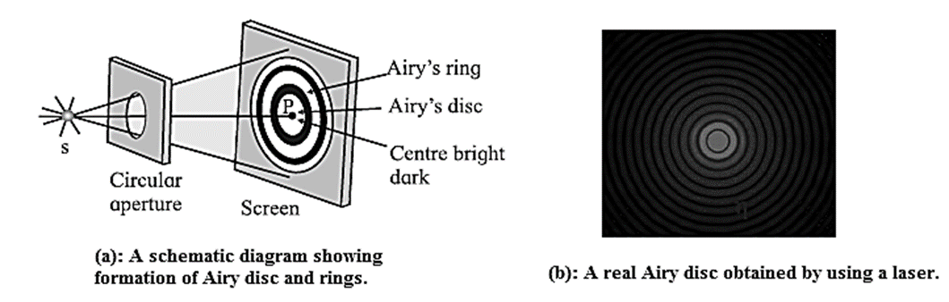
(ii) Pair of Point objects : The objects to be viewed through a microscope are often of the point—size. The diffraction pattern of such objects consists of a central bright spot called the Airy disc and corresponds to the central maximum surrounded by concentric dark and bright rings called Airy rings. Below Fig.(a). If a red laser beam passes through a 90 μm pinhole aperture, the Airy disc and several orders (rings) of diffraction are as shown in below Fig. (b). Click here to View Figure-14
According to Lord Rayleigh, for such objects to be just resolved, the first dark ring of the diffraction pattern of the first object should be formed at the centre of the diffraction pattern of the second object and vice versa. Thus, the minimum separation between the images on the screen should be equal to the radius of the first dark ring. This is applicable to the eye, microscope, telescope, etc.
Resolving Power of a Microscope:
The limit of resolution of a microscope is the least separation between two-closely spaced points on an object which are just resolved when viewed through the microscope.
The resolving power of a microscope is defined to be the reciprocal of its limit of resolution.
In a compound microscope, the objective lens forms a real, magnified image of an object placed just beyond the focal length of the lens. The objective has a short focal length (for greater magnification) and is held close to the object so that it gathers as much of the light scattered by the object as possible.
Let a be the least separation between two point objects O and O’ viewed through an objective AB of a compound microscope.
The medium between the object and the objective has a refractive index n.
The images of the objects O and O’ are I and I’ respectively.
In this case, the angular separation between the objects, at the objective is 2α.
D is the diameter of the objective AB. Fig. 15(a)
Click here to View Figure-15(a)(b)
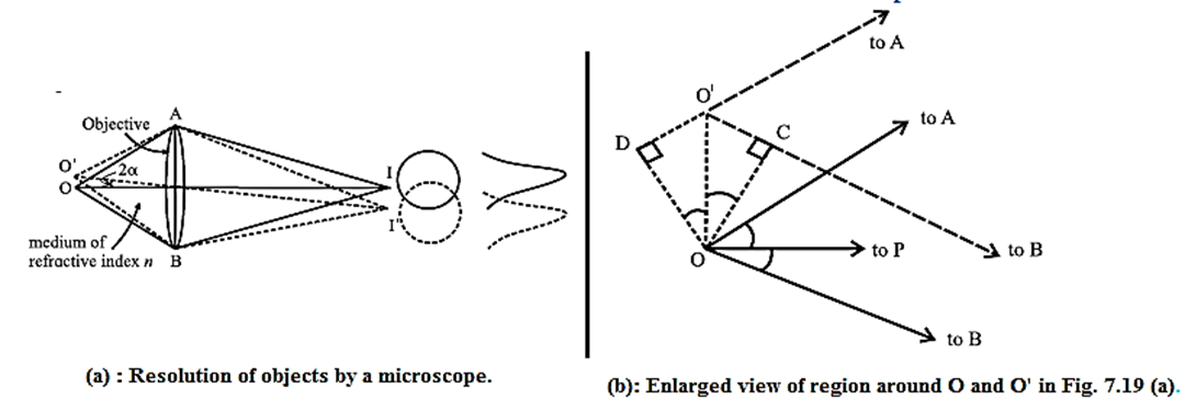
According to the Rayleigh criterion, the first dark ring due to O’ should coincide with I and that of O should coincide with I’. The nature of illumination at a point on the screen is determined by the effective path difference at that point. Let us consider point I to be symmetric with respect to O.
Paths of the extreme rays reaching I from O’ are O’AI and O'BI. The paths AI and BI are equal. Thus, the actual path difference is O’B — O’A.
The enlarged view of the region around O and O’ is as shown in above Fig.(b).
From this, path difference = DO’ + O’C = 2a sin α …(1)
(i) Microscope with a pair of non—luminous objects (dark objects) : In actual practice, the objects O and O’ viewed through a microscope are illuminated by the same source. Often the eyepiece of the microscope is filled with some transparent material of refractive index n. Then the wavelength of light in this material is λn = λ/n, where λ is the wavelength of light in air. In such a set up the path difference at the first dark ring in λn. Thus, from eq. (1), 2a sin α = λn = λ/n ∴ a = \(\frac{λ}{2πsin\,α}=\frac{λ}{2NA}\) ...(2) The factor n sin α is called numerical aperture (NA). The resolving power of the microscope is R = 1/a = \(\frac{2NA}{λ}\)...(3)
(ii) Microscope with self luminous point objects : Applying Abbe’s theory of Airy discs and rings to Fraunhofer diffraction due to a pair of self luminous point objects, the path difference between the extreme rays, at the first dark ring is 1.22 λ , thus, for the requirement of just resolution, 2a sin α = 1.22 λn ∴ a = \(\frac{1.22λ_n}{2sin\,α}\) ∴ a = \(\frac{1.22λ}{2n\,sin\,α}=\frac{0.61λ}{n\,sin\,α}=\frac{0.61λ}{NA} \) …...(4) The resolving power of the microscope is, R = 1/a =\frac{NA}{0.61λ} \) ……(5) When the value of a is minimum, the quality of resolution is high. Thus, the resolving power of a microscope depends directly on the NA and inversely on λ .
Methods to increase in resolving power of microscope :
- The resolving power is increased by, increasing the numerical aperture using oil-immersion objective.
- Illuminating the object with smaller wavelength radiation. But our eyes are not very sensitive to the shorter wavelength blue end of the visible spectrum. Hence, ultraviolet radiation is used for illumination with quartz lenses, but then photographs must be taken to examine the image.
Q. Why microscopes of high magnifying power have oil filled (oil-immersion) objectives.
For better resolution, a should be minimum. This can be achieved by using an oil filled objective which provides higher value of n. The factor n sin α is called the numerical aperture of the objective and the resolving power increases with increase in the numerical aperture. To increase α the diameter of the objective would have to be increased. But this increase in aperture would degrade the image by decreasing the resolving power. Hence, in microscopes of high magnifying power, the object is immersed in oil that is in contact with the objective. Usually cedar wood oil having a refractive index 1.5 (close to that of the objective glass) is used. Closeness of the refractive indices also reduces loss of light by reflection at the objective lens.
Know this :
|
Resolving Power of a Telescope: Telescopes are normally used to see distant stars. For us, these stars are like luminous point objects, and are far off. The resolving power of a telescope is defined as the reciprocal of the angular limit of resolution between two closely-spaced distant objects so that they are just resolved when seen through the telescope. Ref. below Fig Click here to View Figure-16
Consider two stars seen through a telescope. The diameter (D) of the objective lens or mirror corresponds to the diffracting aperture. For a distant point source, the first diffraction minimum is at an angle θ away from the centre such that D sin θ =1.22λ where A is the wavelength of light. The angle θ is usually so small that we can substitute sin θ ≈ θ (θ in radian). Thus, the Airy disc for each star will be spread out over an angular half-width θ = 1.22 λ/D about its geometrical image point. The radius of the Airy disc at the focal plane of the objective lens is r= fθ = 1.22 fλ/D, where f is the focal length of the objective. When observing two closely-spaced stars, the Rayleigh criterion for just resolving the images as that of two point sources (instead of one) is met when the centre of one Airy disc falls on the first minimum of the other pattern. Thus, the angular limit (or angular separation) of resolution is θ = 1.22λ/D ……(1) and the linear separation between the images at the focal plane of the objective lens is y = fθ ...(2) Resolving power of a telescope, R= 1/θ = \(\frac{D}{1.22λ}\) ∴ Resolving power of a telescope depends on Hence, the resolving power can be increased by

Advantages of a large objective lens in an astronomical telescope :
The resolving power is directly proportional to the diameter of the objective lens. Hence, a large objective lens results in a smaller Airy disc and a sharper image.
It collects more of the incident radiation from a distant object which results in a brighter image.
Radio telescope : A radio telescope is an astronomical instrument consisting of a radio receiver and an antenna system used to detect radio-frequency radiation emitted by extraterrestrial sources. The wavelength of radio—frequency radiation is very long. Hence, it is expressed in metre. In order to attain the resolution of an optical telescope, the radio telescope should be very large. A single disc of such large diameters is impracticable. In such cases arrays of antennae spread over several kilometres are used. Giant Metrewave Radio Telescope (GMRT) located at Narayangaon, Pune, Maharashtra uses such an array consisting of 30 dishes of diameter 45 m each. It spreads over 25 km. It is the largest distance between two of its antennae. The highest angular resolution achievable ranges from about 60 arcsec at the lowest frequency of 50 MHZ to about 2 arcsec at 1.4 GHZ.
We reply to valid query.