Notes-Part-1
|
Topics to be Learn : Part-1
|
Introduction :
Magnet :
- The substance / materials which get attracted towards a magnet is known as magnetic materials. These substance also acquire magnetization when attracted towards the magnet.
- This feature of attraction was first seen in a rock in the historically mineral-rich region of Magnesia (modern Turkey).
- This Magnesian rock is where the word "magnet" originated.
- The rock was discovered to align roughly in the north-south direction whether floated on water (by tying it to a piece of wood) or suspended freely.
- It was also known as the leading stone or lodestone since some early travellers utilised this directional ability to determine the geographic north.
- The Magnesian rock is the naturally magnetized iron ore magnetite (Fe3O4). It is hard, black or brownish black with a metallic lustre.
Directional characteristic of a bar magnet :
- When a bar magnet is suspended so as to rotate freely in a horizontal plane, it comes to rest in approximately the North-South direction.
- The end of the magnet directed towards the Earth's geographic North Pole is called the north-seeking pole or the north pole, and the other end which is directed towards the Earth's geographic South Pole is called the south-seeking pole or the south pole.
- The cause for this alignment is seen when we consider the turning moment on a bar magnet suspended in a uniform magnetic induction as shown in below fig.

- The north pole (pole strength + m) and the south pole (pole strength — m) of the bar magnet experience equal and opposite forces of magnitude mB.
- If the lines of action of these two forces are not the same, they constitute a couple whose effect is to produce rotation.
Torque Acting on a Magnetic Dipole in a Uniform Magnetic Field:
When a magnetic dipole of magnetic dipole moment is placed in a uniform magnetic field of induction \(\vec{B}\), it experiences a torque whose magnitude is
τ = MB sin θ
where θ is the smaller angle between the magnetic axis and \(\vec{B}\).
When the dipole is placed with its axis at right-angles to the field, i.e, θ = 90°,
τ = MB or M = τ/B
This is the defining equation for the magnetic dipole moment.
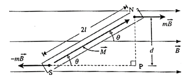
Expression for the torque acting on a magnetic dipole placed in a region of uniform magnetic induction. Consider a magnetic dipole consisting of two point poles of pole strength m a distance 2l apart with its axis inclined at an angle θ to a uniform magnetic field of induction \(\vec{B}\) see fig. The magnetic force on the positive (or north) pole is m , while that on the negative (or south) pole is —m . These two forces, equal in magnitude, opposite in direction and separated by a finite distance, constitute a couple which tends to line up the magnetic dipole moment with the field \(\vec{B}\). The torque of the couple in the clockwise sense in above Fig. in magnitude, is τ = (mB) d where d is the distance between the lines of action of the forces. τ = (mB) 2l sin θ = MB sin θ .... ( as \(m=\frac{M}{2l}\)) Expressed as a vector product, \(\vec{τ}\) = \(\vec{M}× \vec{B}\) The torque has a maximum magnitude, (m2l) B, when sin θ = 1, i.e., when the magnet is perpendicular to the field. The torque vanishes when the magnet is parallel to the field, where sin θ = 0.
Magnetic potential energy :
Due to the torque the bar magnet will undergo rotational motion. Whenever a displacement (linear or angular) is taking place, work is being done. Such work is stored in the form of potential energy in the new position.
The work done is stored as the magnetic potential energy, also called its orientation energy.
In a finite angular displacement from 0 to θ, the magnetic potential energy
Um = \(\int_{0}^{θ} τ(θ)dθ\)
Um = \(\int_{0}^{θ} MB\,sinθ\,dθ\)
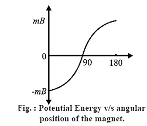
Um = −MB cos θ
Case 1 : When θ = 0°, cos θ = cos 0° = 1, Um = −MB. At this position, the magnetic moment of the bar magnet is lined up with the field and its magnetic potential energy is minimum. This is its most stable equilibrium position.
Case 2 : When θ = 180°, cos θ = cos 180° = −1, Um = MB. At this position, the magnetic moment is antiparallel to the field and its magnetic potential energy is maximum. This is its most unstable position.
Case 2 : When θ = 90°, cos θ = cos 90° = 0, Um = 0. At this position, the bar magnet is perpendicular to the magnetic field. Its magnetic potential energy is zero.
Expression for the time period of angular oscillations of a bar magnet kept in a uniform magnetic field : Consider a bar magnet of magnetic dipole moment \(\vec{M}\) suspended by a light twistless fibre in a uniform magnetic field \(\vec{B}\) in such a way that it is free to rotate in a horizontal plane. In the rest position θ = 0, \(\vec{M}\) is parallel to \(\vec{B}\). If magnet is given a small angular displacement θ from its rest position and released, the magnet performs angular or torsional oscillations about the rest position. Let I be the moment of inertia of the bar magnet about the axis of oscillation and α the angular acceleration. The deflecting torque (in magnitude) is. τd = I α = \(I\frac{d^2θ}{dt^2}\) ……. (1) However, the restoring torque tries to bring back the oscillating bar magnet in the rest position. The restoring torque (in magnitude) is, τr = −MB sin θ ……. (2) The minus sign in Eq. (2) indicates that restoring torque is opposite in direction to the angular deflection. In equilibrium, both the torques balance each other. From Eqs. (1) and (2), \(I\frac{d^2θ}{dt^2}\) = −MB sin θ …….(3) For small θ, sin θ = θ. Thus, Eq. (3) can be written as \(I\frac{d^2θ}{dt^2}\) = −MB θ \(\frac{d^2θ}{dt^2}\) = \(\frac{MB}{I}θ\) ……..(4) Eq. (4) represents angular simple harmonic motion. Writing ω2 = \(\frac{MB}{I}\), the angular frequency ω of the motion is ω = \(\sqrt{\frac{MB}{I}}\) …….(5) The time period of oscillations of the bar magnet is T = 2π/ω = 2π\(\sqrt{\frac{I}{MB}}\) …..(5) This is the required expression.
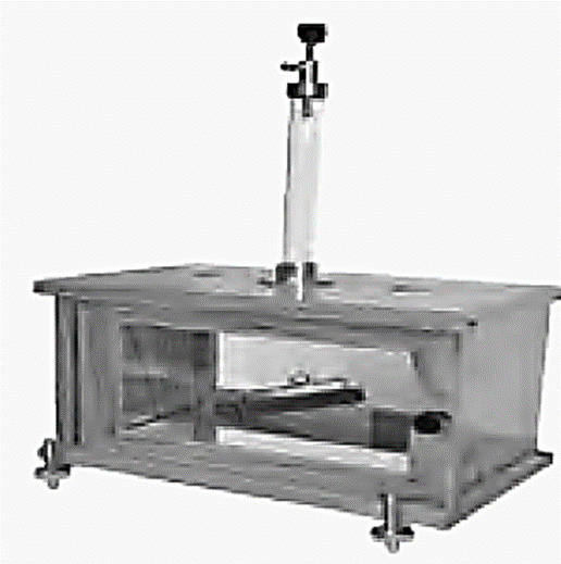
| Vibration Magnetometer:
Vibration Magnetometer is used for the comparison of magnetic moments and magnetic field. This device works on the principle, that whenever a freely suspended magnet in a uniform magnetic field, is disturbed from its equilibrium positions, it starts vibrating about the mean position. It can be used to determine horizontal component of Earth's magnetic field.
|
Location of Magnetic poles of a Current Carrying Loop:
A current carrying conductor produces magnetic field and if we bend the conductor in the form of loop, this loop, behaves like a bar magnet
Origin of Magnetism in Materials:
Negatively charged electrons are spinning around the nucleus in an atom (consisting of protons and neutrons). The electrons that are in the atom's outermost orbit control its chemical characteristics. The same is true of magnetic characteristics.
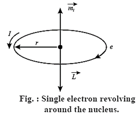
Expression for orbital magnetic moment of an electron rotating about the nucleus in an atom : In the Bohr model of a hydrogen atom, the electron of charge —e performs a uniform circular motion around the positively charged nucleus. Let r, v and T be the orbital radius, speed and period of motion of the electron. Then, T = 2πr/v …….(1) Therefore, the orbital magnetic moment associated with this orbital current loop has a magnitude, I = e/T = \(\frac{ev}{2πr}\) Therefore, the magnetic dipole moment associated with this electronic current loop has a magnitude M0 = current x area of the loop = I(πr2) = \(\frac{ev}{2πr}×πr^2\)=\(\frac{1}{2}evr\) ……..(3) Multiplying and dividing the right hand side of the above expression by the electron mass me M0 =\(\frac{e}{2m_e}(m_evr)\) = \(\frac{e}{2m_e}L_0\) …..(4) where L0 = mevr is the magnitude of the orbital angular momentum of the electron. \(\vec{M_0}\) is opposite to \(\vec{L_0}\) ∴ \(\vec{M_0}\) = \(\frac{e}{2m_e}\vec{L_0}\) …..(5) which is the required expression According to Bohr’s second postulate of stationary orbits in his theory of hydrogen atom, the angular momentum of the electron in the nth stationary orbit is equal to \(n\frac{h}{2π}\) , where h is the Planck constant and n is a positive integer. Thus, for an orbital electron, L0 = mev r = \(\frac{nh}{2π}\) Substituting for L0 in Eq. (4), M0 = \(\frac{enh}{4πm_e}\) For n = 1 M0 = \(\frac{enh}{4πm_e}\) The quantity \(\frac{enh}{4πm_e}\) is a fundamental constant called the Bohr magneton, μB. μB = 9.274 x 10⁻²⁴ I/T (or A-m2) = 5.788 x 10⁻⁵ eV/T.
| Know This :
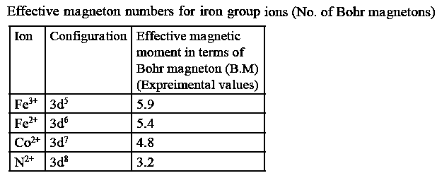
The effective magnetic moments of a few iron group ions are shown below in terms of the Bohr magneton (μB). In a few instances, the orbital and spin angular momenta are equally responsible for the magnetic moment.
|
Gyromagnetic ratio of an orbital electron :
The ratio of the magnitude of the orbital magnetic moment to that of the orbital angular momentum of an electron in an atom is called its gyromagnetic ratio γ0. If \(\vec{M_0}\) is the orbital magnetic moment of the electron with orbital angular momentum .
γ0 = M0/L0 = e/2me
where e and me are the electronic charge and electron mass, respectively.
SI unit : The coulomb per kilogram (C/kg).
Remember : Gyromagnetic ratio of electron γ0 = 8.794 x 10¹⁰ C/kg. The gyromagnetic ratio of electron spin is nearly twice that of an orbital electron.
| Know This :
(1) Two possible orientations of spin angular momentum ( ) of an electron in an external magnetic field. Note that the spin magnetic dipole moment is in a direction opposite to that of the angular momentum.
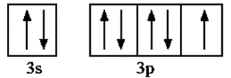
(2) Let us see whether the given atom has paired electron or unpaired electrons in the outermost orbit. We will follow three steps- 1) Write electronic configuration 2) Draw valence orbital 3) Identify if unpaired electron exist Ex. Chlorine Cl ( it has total 17 electrons) 1) electronic configuration 1s2 2s2 2p6 3s2 3p5 2) ignoring inner completely filled orbitals and just considering valence electrons.
3) There is one unpaired electron. In a similar manner study Fe, Zn, He, B, Ni and draw your conclusions. |

Magnetization and Magnetic Intensity:
Atoms with unpaired electrons have a net magnetic dipole moment. The bulk material is made up of a large number of such atoms each having an inherent magnetic moment. The magnetic dipole moments are randomly oriented and hence the net dipole moment of many of the bulk materials is zero.
For some materials (such as Fe3O4), the vector addition of all these magnetic dipole moments may not be zero. Such materials have a net magnetic moment.
When such a material is placed in an external magnetic field of induction \(\vec{B_0}\), the field exerts a torque on each atomic magnet. These torques tend to align the magnetic moments with the applied field. Due to this, the material as a whole acquires a net magnetic moment \(\vec{M}_{net}\) along \(\vec{B_0}\) and the material is said to be magnetized.
The ratio of magnetic moment to the volume of the material is called magnetization \(\vec{M_z}\) of the material .
\(\vec{M_z}\) = \(\frac{\vec{M}_{net}}{V}\)
where V is the volume of the material.
Even when the atomic magnetic moment is zero, application of magnetic field induces magnetism in the material. In this case, the magnetization has direction opposite to that of the applied field.
Dimensions : [Magnetization] = [magnetic moment]/[volume] = [L2I]/[L3] = [L-1I]
SI unit : The ampere per metre (A/m).
Magnetization of a magnetic material placed in a solenoid : Consider a rod of such a material with some net magnetization, placed in a solenoid with n turns per unit length, and carrying current I. Magnetic field inside the solenoid is given by B0 = μ0nI …… (1) where n = \(\frac{N}{2πr}\) is the number of turns per unit length and μ0 is the permeability of free space. When a core of magnetic material (such as iron) is present, the magnetic field within the solenoid due to the current in the winding magnetizes the material of the core. with the core, the magnetic induction \(\vec{B}\) inside the solenoid is greater than \(\vec{B_0}\), so that B = B0 + Bm where Bm is the contribution of the iron core. Bm is proportional to the magnetization MZ of the material. Bm = μ0MZ ….(3) While discussing magnetic materials, it is customary to call \(\frac{B_0}{μ_0}\) as the magnetizing field or magnetic field intensity, denoted by H, which produces the magnetization. B0 = μ0H …..(4) Substituting for B0 and Bm in Eq. (1), B = μ0H + μ0MZ = μ0(H + MZ) …..(5) For materials in which the magnetization is proportional to the magnetic intensity, MZ ∝ H or MZ = χmH ……(6) where the constant of proportionality χm is called the magnetic susceptibility. ∴ B = μ0(H + χmH) = μ0(1 +χm)H = μH …..(7) where μ = μ0(1 +χm) is called the permeability of the material. Remember : (1) MZ ∝ H only for diamagnetic and para magnetic materials. Among ferromagnetic materials, the linear relation in Eq. (6) holds good only for initial magnetization of magnetically of softer materials; for magnetically harder materials, MZ is not a single-valued function of H, and depends on the magnetic intensity that the material has been previously exposed to (a phenomenon known as hysteresis). (2) H is defined for convenience; B is more fundamental.
Magnetic intensity : The magnetic intensity is defined as the magnetic induction in an isotropic medium divided by the permeability of the medium.
The magnetic intensity is a quantitative characteristic of a magnetic field independent of the magnetic properties of the medium. In a medium, it determines the contribution to the magnetic induction in the medium by the external magnetic field.
Dimensions : Within a toroid without a core, which has n windings per unit length carrying a current I, the magnetic intensity, H = nI. [L-1][I] = [L-1I]
SI unit : The ampere per metre (A/ m).
Magnetic susceptibility of a medium : The magnetic susceptibility of a medium is a dimensionless quantity which signifies the contribution made by the medium when subjected to a magnetic field to the magnetic induction inside the medium. For a material in which the magnetization Mz is proportional to the magnetic intensity H, the magnetic susceptibility of the medium is χm = Mz/H It is equal to the fractional change in the magnetic induction due to the medium.
Relative permeability of a medium:
The ratio of the permeability of a medium to that of free space is called the relative permeability of the medium, denoted by μr
μr = μ/μ0 = 1 + χm
χm is the magnetic susceptibility of a medium
Relation between permeability and magnetic susceptibility of a medium :
If χm is the magnetic susceptibility of a medium, the permeability of the medium is
μ = μ0(1 +χm)
where μ0 is the permeability of free space.
| Permeability and Permittivity:
Magnetic permeability is analogous to electric permittivity, both indicating the extent to which a material permits a field to pass through or permeate into the material. For a superconductor, χ = —1 which makes μ = 0, so that a superconductor does not allow magnetic field lines to pass through it. Magnetic susceptibility (χ), analogous to electrical susceptibility, is a measure of the response of a given material to an applied magnetic field. That is, it indicates the extent of the magnetization produced in the material when it is placed in an external magnetic field. χ is positive when the atomic dipole moments align themselves in the direction of the applied field; χ is negative when the atomic dipole moments align antiparallel to the field. χ is large for soft iron (χ > 1000). |
We reply to valid query.