Notes-Part-1
|
Topics to be Learn : Part-1
|
Introduction :
There are two types of supplies of electricity:
- DC, the direct current which has fixed polarity of voltage (the positive and negative ends of the power supply are fixed).
- AC, the alternating current for which the polarity of the voltage keeps changing periodically.
- The electricity is typically supplied as AC due to its low cost and ease of transportation.
- Appliances like TVs, computers, transistor radios, and others that we use at home or in the workplace. Utilize a rectifier or similar device to convert AC to DC.
- Some of the devices, use in homes and offices, such as the television, computer, transistor, and radio, convert AC to DC using a device called a rectifier.
- Some household appliances run directly on AC, including fans, refrigerators, air conditioners, induction heaters, coil heaters, etc. These devices almost all contain parts like an inductor and a capacitor.
AC Generator:
Alternating emf : An alternating emf that varies sinusoidally with time is given by e = e0 sin ωt, where e0 is the maximum value of the emf, called the peak value, and ω is the angular frequency of the emf.
ω = 2πf = 2π/T
where f is the frequency of the emf, expressed in Hz, and T is the periodic time of the emf, expressed in second.

From the graph it can be seen that the direction of the emf is reversed after every half revolution of the coil. This type of emf is called the alternating emf and the corresponding current is called alternating current.
Average and RMS values:
Average or mean value of an alternating emf :
The average or mean value of an alternating emf is defined as its average value over half cycle (because the average value over one cycle is zero) and is given as
eav = \(\frac{\int_{0}^{T/2}e_0\,sinωt\,dt}{T/2}\) = \(\frac{2e_0}{T}\int_{0}^{T/2}sinωt\,dt\) =
= \(\frac{2e_0}{T}[\frac{-cosωt\,dt}{ω}]_0^{T/2}\)
= \(\frac{2e_0}{ωT}[-cos\frac{2π}{T}(\frac{T}{2})-(-1)]\)
= \(\frac{2e_0}{ωT}(1+1)\)
= \(\frac{2e_0}{\frac{2π}{T}T}(2)\)
= \(\frac{2}{π}e_0\) = 0.6365 e0
Root-mean-square (or rms) value :
The root mean square (rms) value of an alternating current i is, by definition,
irms = \([\frac{\int_{0}^{I}i^2\,dt}{T}]^{1/2}\), where T is the periodic time, i.e., time for one cycle.
If i = i0 sin ωt,
\(\int_{0}^{T}i^2\,dt\) = \(\int_{0}^{T}i^2\,sin^2ωt\,dt\)
Now \(\int_{0}^{T}i^2\,sin^2ωt\,dt\) = \(\int_{0}^{T}\frac{1-cos2ωt}{2}dt\)
= \(\int_{0}^{T}\frac{1}{2}dt-\int_{0}^{T}\frac{cos2ωt}{2}dt\)
= \(\frac{T}{2}-\frac{1}{2}(\frac{sin2ωt}{2ω})_{0}^{T}\)
= \(\frac{T}{2}-\frac{1}{4ω}(sin2ωT-sin0)\)
= \(\frac{T}{2}-\frac{1}{4ω}[sin2(\frac{2π}{T})T-0)\)
= \(\frac{T}{2}-\frac{1}{4ω}[0-0]\) = \(\frac{T}{2}\)
∴ \(\int_{0}^{T}i^2dt=i_0^2(\frac{T}{2})\)
∴ irms = \([\frac{i_0^2}{2}]^{1/2}\) = \(\frac{i_0}{\sqrt{2}}\)
= \(\frac{i_{peak}}{\sqrt{2}}\)≈ 0.707 i0
irms is also called the effective value or virtual value of the alternating current. In one cycle, the heat produced in a resistor by I = i0 sin ωt is the same as that produced by a direct current (dc) equal to irms.
iav (over half cycle) = \(\frac{2}{π}i_0\) and irms = \(\frac{i_0}{\sqrt{2}}\)
∴ iav (over half cycle) = \(\frac{2}{π}(\sqrt{2}i_{rms})\) = \(\frac{2\sqrt{2}}{π}i_{rms}\)
Expression for the heat produced in the resistor in one complete cycle :
The heat produced in a resistor of resistance R in one complete cycle.
H = \(\int_{0}^{T}i^2Rdt=R\int_{0}^{T}i^2sin^2ωt\,dt\)
as i = i0 sin ωt
Now, \(\int_{0}^{T}i^2\,sin^2ωt\,dt\) = \(\int_{0}^{T}\frac{1-cos2ωt}{2}dt\)
= \(\int_{0}^{T}\frac{1}{2}dt-\int_{0}^{T}\frac{cos2ωt}{2}dt\)
= \(\frac{T}{2}-\frac{1}{2}(\frac{sin2ωt}{2ω})_{0}^{T}\)
= \(\frac{T}{2}-\frac{1}{4ω}(sin2ωT-sin0)\)
= \(\frac{T}{2}-\frac{1}{4ω}[sin2(\frac{2π}{T})T-0)\)
= \(\frac{T}{2}-\frac{1}{4ω}[0-0]\) = \(\frac{T}{2}\)
∴ H = \(\frac{Ri_0^2T}{2}=Ri_{rms}^{2}T\)
Now, ω = 2πf = 2π/T, where f is the‘ frequency and T is the period of AC.
∴ H = \(Ri_{rms}^{2}/f=Ri_{rms}^{2}\frac{2π}{ω}\)
| Alternating voltages and current go through all values between zero and the peak value in one cycle.
Peak value (i0) : Peak value of an alternating current (or emf) is the maximum value of the current (or emf) in either direction. |
Remember :
|
Phasors:
Phasor :
A phasor is a rotating vector that represents a quantity varying sinusoidally with time.
Phasor diagram :
A diagram that represents a phasor is called phasor diagram. Consider an alternating emf e = e0 sin ωt.
The phasor representing it is inclined to the horizontal axis at an angle ωt and rotates in an anticlockwise direction as shown in Fig.

The length (OP) of the arrow \(\vec{OP}\) represents the peak value (maximum value), e0, of the emf.
For e = e0 sin ωt, the projection of on the y-axis gives the instantaneous value of the emf.
In Fig. a, OR = e0 sin ωt.
For e = e0 cos ωt, the projection of \(\vec{OP}\) on the x-axis gives the instantaneous value of the emf.
In Fig. b OQ = e0 cos ωt.
We can use the laws of vector addition (Phasor digram) to add the harmonically varying quantities by representing them as rotating vectors.
Different Types of AC Circuits:
(a) AC voltage applied to a resistor:
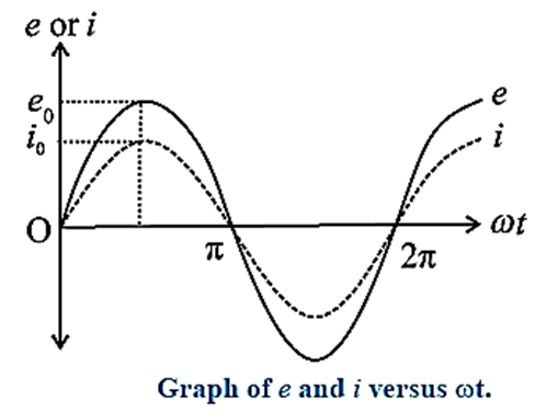
Below Fig. shows an alternating emf e = e0 sin ωt applied to a resistor of resistance R.

e0 is the peak value and co is the angular frequency of the emf. The instantaneous current through the resistor is i = i0 sin ωt, where i0 is the peak value of the current.
Here, i and e are always in phase.
For ωt = 0, sin ωt = 0, e=0, i=0;
for ωt = π/2, sin ωt = 1, e = e0, I = i0;
for ωt = π, sin ωt =0, e = 0, I = 0;
for ωt =3π/2, sin ωt = —1, e = — e0, i= — i0;
for ωt =2π, sin ωt = 0, e = 0, i = 0.
Below Figure shows variation of e and i with ωt.
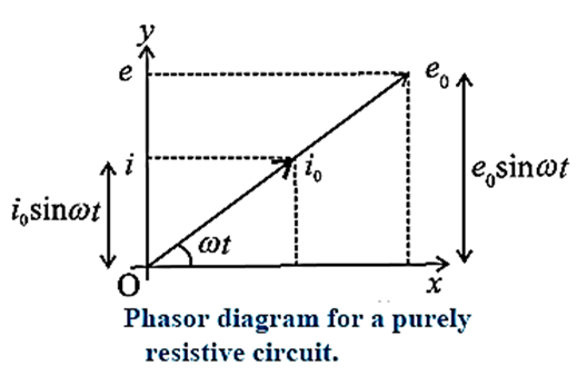
Phasor diagram:
In the AC circuit containing R only, current and voltage are in the same phase, hence both phasors for i and for e are in the same direction making an angle ωt with OX. Their projections on vertical axis give their instantaneous values.
The phase angle between alternating current and alternating voltage through R is zero as shown in below Fig.
(b) AC voltage applied to an Inductor:
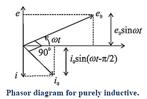
In an AC circuit containing a pure inductor, the voltage is ahead of current by π/2 rad in phase :
Proof :
Let us now connect the source of alternating emf to a circuit containing pure inductor (L) only as shown in Fig.
Let us assume that the inductor has negligible resistance. The circuit is therefore a purely inductive circuit.
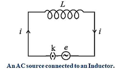
Suppose the alternating emf supplied is represented by
e = e0 sin ωt
On closing the key K, an emf is induced in the inductor as the magnetic flux linked with it changes with time. This emf opposes the applied emf and according to the laws of electromagnetic induction by Faraday and Lenz, we have,
e' = \(L\frac{di}{dt}\) .....(1)
where e’ is the induced emf and i is the current through the inductor. To maintain the current, e and e’ must be equal in magnitude and opposite in direction.
According to Kirchh0ff’s voltage law, as the resistance of the inductor is assumed to be zero, we have,
e = −e’ = \(L\frac{di}{dt}\) …….(2)
∴ \(L\frac{di}{dt}\) = e/L = (e0 sin ωt)/L
∴ ∫ di = \(\int \frac{e_0\,sin\,ωt}{L}dt\)
∴ i = \(-\frac{e_0}{ωL}cos\,ωt+C\)
where C is the constant of integration. C must be time independent and have the dimension of current. As e oscillates about zero, i also oscillates about zero and hence there cannot be any time independent component of current.
∴ C = 0. ∴ i = \(-\frac{e_0}{ωL}cos\,ωt\) = \(-\frac{e_0}{ωL}sin(\frac{π}{2}-ωt)\) …….(3)
∴ i = \(\frac{e_0}{ωL}sin(ωt-\frac{π}{2})\) … [ as sin(-θ) = − sin θ]
From Eq. (3), ipeak = i0 = \(\frac{e_0}{ωL}\)
∴ i = \(i_0sin(ωt-\frac{π}{2})\)
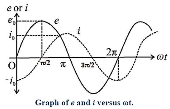
Comparison of this equation with e = e0 sin ωt shows that e leads i by π/2 rad, i.e., the voltage is ahead of current by π/2 rad in phase.
Variation of the emf and current with ωt :
Phasor diagram:
The phasor representing peak emf e0 makes an angle ωt in anticlockwise direction from horizontal axis. As current lags behind the voltage by π/2, so the phasor representing i0 is turned clockwise with the direction of e0 as shown in Fig.
In this case, e = e0 sin ωt and i = \(i_0sin(ωt-\frac{π}{2})\) where i0 = \(\frac{e_0}{ωL}\) and L is the inductance of the inductor.
Inductive Reactance (XL):
When an alternating emf e = e0 sin ωt is applied to a pure inductor of inductance L, the current in the circuit is i = \(i_0sin(ωt-\frac{π}{2})\), where i0 = \(\frac{e_0}{ωL}\)
In the case of a pure resistor of resistance R,
i = i0 sin ωt for e = e0 sin ωt, and i0 =\(\frac{e_0}{R}\)
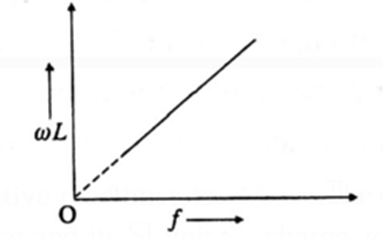
Comparison of Eqs. i0 = \(\frac{e_0}{ωL}\) and i0 = \(\frac{e_0}{R}\) shows that ωL is the resistance offered by the inductor to the applied alternating emf. It is called the reactance. It increases linearly with the frequency f because ωL = 2πfL (...ω = 2π/T = 2πf).
This is illustrated in the following figure. ωL is denoted by XL.
Behaviour of pure inductor :
Inductive reactance = 2πfL.
- If the frequency (f) of the applied emf is very high, the inductive reactance (for reasonable value of inductance L) will be very high. Hence, the current through the inductor will be very low (for reasonable value of peak emf). Hence, it will practically block AC.
- For very low frequency (f), 2πfL is low and hence the inductor will behave as a good conductor.
(c) AC voltage applied to a capacitor:
Let us consider a capacitor with capacitance C connected to an AC source with an emf having instantaneous value e = e0 sin ωt. This is shown in Fig.
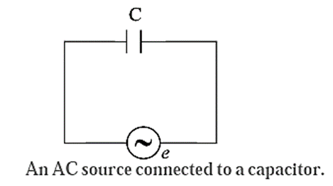
The plates of the capacitor get charged due to the applied voltage. As the alternating voltage is reversed in each half cycle, the capacitor is alternately charged and discharged. If q is the charge on the capacitor, the corresponding potential difference across the plates of the capacitor is V = q/C, ∴ q = CV.
q and V are functions of time, with V = e = e0 sin ωt. The instantaneous current in the circuit is
i = dq/dt = \(\frac{d}{dt}(CV)\) = \(C\frac{dV}{dt}\) = \(C\frac{d}{dt}(e_0\,sinωt)\) = ωCe0 cos ωt
∴ i = \(\frac{e_0}{(1/ωC)}sin(ωt+\frac{π}{2})\) = \(i_0\,sin(ωt+\frac{π}{2})\)
Where i0 = \(\frac{e_0}{(1/ωC)}\) is the peak value of the current,
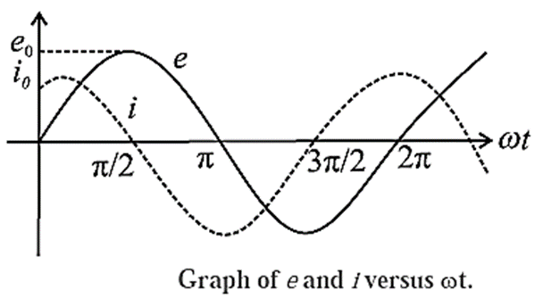
From Eq. e = e0 sin ωt and Eq. \(i=i_0\,sin(ωt+\frac{π}{2})\) we find that in an AC circuit containing a capacitor only, the alternating current i leads the alternating emf e by phase angle of π/2 radian as shown in above graph.
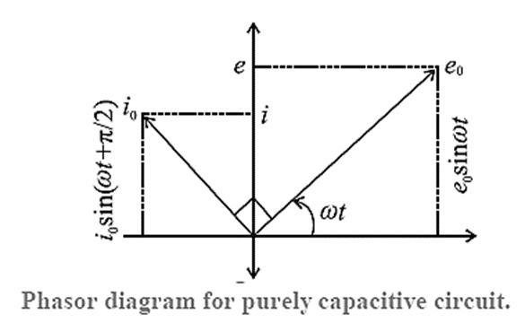
Phasor diagram:
The phasor representing peak emf (e0) makes an angle ωt in anticlockwise direction with respect to horizontal axis. As current leads the voltage by 90°, the phasor representing i0 current is turned 90° anticlockwise with respect to the phasor representing emf e0. The projections of these phasors on the vertical axis gives instantaneous values of e and i.
Capacitive reactance : When an alternating emf e = e0 sin ωt is applied across a pure (an ideal) capacitor of capacitance C, the peak current through the circuit is i0 = \(\frac{e_0}{1/ωC}\) where ω is the angular frequency of AC. The quantity 1/ωC (denoted by XC) is the resistance offered by the capacitor to AC.
∴ Xc = \(\frac{1}{ωC}\) = \(\frac{1}{2πfC}\)
It is called capacitive reactance. It has the same dimensions and unit as resistance and its SI unit is ohm (Ω).
In a DC circuit, f = 0 ∴ XC = \(\frac{1}{2πfC}\) = ∞, The current through the capacitor will be zero. Thus, capacitor blocks DC and acts as open circuit while it passes AC of high frequency.
Behaviour of pure (an ideal) capacitor :
- If the frequency (f) of the applied emf is very low, the capacitive reactance (for reasonable value of capacitance C) will be very high and hence the current through the circuit will be very low (for reasonable value of peak emf).
- For very high frequency, f, Xc is very small. Hence, for very high frequency AC supply, a capacitor behaves like a pure conductor.
Comparison between resistance and reactance :
| resistance | reactance |
| Resistance, which opposes the flow of charges (current), can be found in both DC and AC circuits. | Reactance is a term that only appears in an AC circuit. When an inductor or capacitor is used, it happens. |
| In a purely resistive circuit, current and voltage are always in phase. | There is a nonzero phase difference between current and voltage when reactance is not zero. |
| Resistance does not depend on the frequency of AC. | Reactance depends on the frequency of AC. In case of an inductor, reactance increases linearly with frequency. In case of a capacitor, reactance decreases as frequency of AC increases; it is inversely proportional to frequency. |
| Resistance gives rise to production of Joule heat in a component. | In a circuit with pure reactance, there is no production of heat. |
(d) AC circuit containing resistance inductance and capacitance in series (LCR circuit):
Now let us consider the total opposition offered by a resistor, pure inductor and capacitor connected in series with the alternating source of emf as shown in Fig.
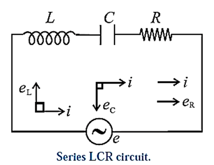
Let a pure resistor R, a pure inductance L and an ideal capacitor of capacitance C be connected in series to a source of alternative emf. As R, L and C are in series, the current at any instant through the three elements has the same amplitude and phase. Let it be represented by i = i0 sin ωt.
The voltage across the resistor, eR = Ri, is in phase with the current. The voltage across the inductor, eL = XLi, leads the current by π/2 rad and that across the capacitor, ec = XCi, lags behind the current by π/2 rad. This is shown in the phasor Diagram (Fig.).
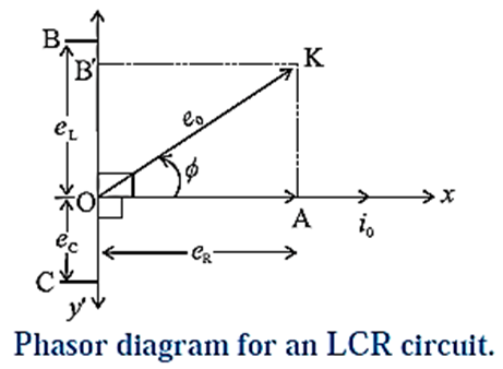
From this figure, e02 = eR2 + (eL − eC)2
= R2i02 + (XLi0 − XCi0)2 = i02 [R2 + (XL − XC)2]
∴ e0 = \(i_0\sqrt{R^2+(X_L-X_C)^2}\) = i0Z, Where
Z = \(\frac{e_0}{i_0}\) = \(\sqrt{R^2+(X_L-X_C)^2}\) is the effective resistance of the circuit. It is called the impedance.
Expression for the phase difference between the emf and the current :
From above Phasor diagram
sin Φ = \(\frac{e_L-e_C}{e_0}\) = \(\frac{(ωL-\frac{1}{ωC})i_0}{Zi_0}\) = \(\frac{ωL-\frac{1}{ωC}}{Zi_0}\)
cos Φ = \(\frac{e_R}{e_0}\) = \(\frac{Ri_0}{Zi_0}\)=\(\frac{R}{Z}\)
∴ tan Φ = \(\frac{sinΦ}{cosΦ}\) = \(\frac{ωL-\frac{1}{ωC}}{R}\)
∴ Φ = \(tan^{-1}(\frac{ωL-\frac{1}{ωC}}{R})\)
This is the phase difference between the emf and the current.
Particular cases :
- For ωL > 1/ωC tan Φ is positive. Here, the emf leads the current by phase angle Φ.
- For ωL < 1/ωC , tan Φ is negative. Here, the emf lags behind the current by phase angle Φ.
- For ωL = 1/ωC, tan Φ = 0. Here, the emf and current are in phase (Φ = 0) as the circuit is purely resistive]
Term impedance :
In an AC circuit containing resistance and inductance and/or capacitance, the effective resistance offered by the circuit to the flow of current is called impedance. It is denoted by Z.
For an LCR series circuit,
Z = \(\sqrt{R^2+(ωL-\frac{1}{ωC})^2}\)
ω = 2πf is the angular frequency and f is the frequency of AC.
Here, in the absence of a capacitor,
Z = \(\sqrt{R^2+ω^2l^2}\), and in the absence of an inductor,
Z = \(\sqrt{R^2+\frac{1}{ω^2C^2}}\)
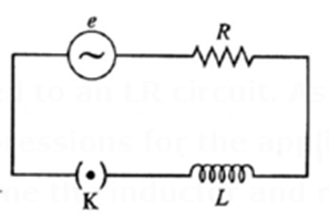
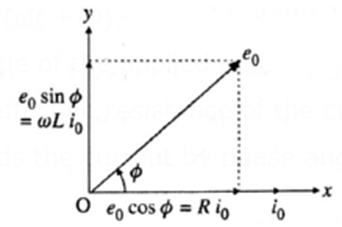
Q. An alternating emf is applied to an LR circuit. Assuming the expression for the current, obtain the expressions for the applied emf and the effective resistance of the circuit. Assume the inductor and resistor to be ideal. Draw the phasor diagram showing the emf and current.
Ans : Figure shows a source of alternating emf (e), key K, ideal inductor of inductance L and ideal resistor of resistance R connected to form a closed series circuit. Ignoring the resistance of the source and the key, we have, e = Ri + L\(\frac{di}{dt}\) ……(1) where Ri is the potential difference across R and L is the potential difference across L. For i = i0 sin ωt. \(\frac{di}{dt}\) = i0ω cos ωt. ∴ e = Ri0 sin ωt + i0ωL cos ωt. 2 2 2 R - COL Let Z = \(\sqrt{R^2+ω^2l^2}\) , cos Φ = R/Z and sin Φ = ωL/Z e = Zi0 sin ωt cos Φ + Zi0ωL cos ωt sin Φ. = Zi0 sin (ωt + Φ) = e0 sin (ωt + Φ). where e0 = Zi0 is the peak value of the applied emf. Z = e0/i0 = \(\sqrt{R^2+ω^2l^2}\) is the effective resistance of the circuit. It is called the impedance. Here, the emf leads the current by phase angle Φ. Φ = cos−1(R/Z) = sin−1(ωL/Z)
We reply to valid query.