Notes Part-1
|
Topics to be Learn : Part-1
|
Introduction :
The valence electrons are the conduction electrons or free electrons constituting an electric current when a potential difference is applied across the conductor.
Electric current :
Definition :Electric current is defined as the time rate of flow of electric charge through a cross sect-ion of a conductor or a semiconductor.
Consider a gas made of positively charged and negatively charged particles confined to a certain regi on of space, Fig. These particles move at random.
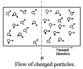
In the figure, P is a plane perpendicular to the plane of the figure. Suppose we apply electric field such that there is net flow of charge across P in the forward direction.
If, in time t, positive charge flowing in the forward direction is q+ and negative charge flowing in the forward direction is q—, the net charge flowing in the forward direction is q = q+ — q—. In a steady flow, q ∝ t and the ratio \(\frac{q}{t}\) is called the electric current (or, simply, current), denoted by I.
Thus, I = \(\frac{q}{t}\)
SI unit of the current is ampere (A), that of the charge and time is coulomb (C) and second (s) respectively.
If the flow is not steady, instantaneous current [current at time t]
I(t) = \(\lim\limits_{Δt\to 0} \frac{Δq}{Δt}=\frac{dq}{dt}\), where Δq is the net charge crossing plane P in time interval Δt between t and t + Δt.
Note : Charged particles may be positive ions, negative ions, electrons, or holes (in a semiconductor)
Ampere : Assuming a constant charge flow, if one coulomb of charge flows through any cross section of a conductor in one second, the current through the conductor equals one ampere.
- 1 miliampere(mA) = 10—3A,
- 1 microampere (μA) = 10—6A,
- 1 nanoampere (nA) = 10—9 A.
Flow of current through a conductor :
- A current can be generated by positively or negatively charged particles. In an electrolyte, both positively and negatively charged particles take part in the conduction.
- In a metal, the free electrons are responsible for conduction. These electrons flow and generate a net current under the action of an applied electric field. As long as a steady field exists, the electrons continue to flow in the form of a steady current.
- In the absence of an external electric field, they move with different speeds in different directions and undergo frequent collisions like molecules of an ideal gas. On an average, just as many electrons move in one direction as in the opposite direction, so that there is no net flow of charge. Hence, there is no current in the conductor.
- The situation is modified when an electric field is applied across the conductor, using a cell or battery. Then, between successive collisions, an electron is accelerated and acquires a velocity component opposite to the electric field because of its negative charge.
- Thus, in addition to random thermal motion, the free electrons move slowly, or drift, in the direction opposite to the electric field constituting an electron current in that direction. The conventional current is taken to be opposite indirection to the electron current.
Know This :
|
Drift speed :
Current density : The current density in a conductor is the current per unit area of cross section of the conductor. It has the direction same as that of conventional current.
If I is the steady current through a conductor of cross-sectional area A, the magnitude of the current density in the conductor is J = I/A
The SI unit of current is the ampere and that of area is square metre.
Hence, the SI unit of current density = the ampere/(metre)2 [A/m2].
Drift speed of electrons in a conductor :
Below Figure (a) shows random motion of free electrons in a conductor, such as a copper wire, in the absence of applied electric field. Hence, there is no net transport of charge across any section of the conductor and consequently, no current. Positive ions are not shown in the diagram as they simply vibrate about their mean positions.
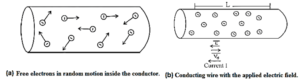
Figure (b) shows what happens when an electric field \(\vec{E}\) is applied parallel to the length of the conductor. The free electrons are acted upon by an electric force in the direction opposite to that of \(\vec{E}\). Hence, they move, i.e., drift with a speed vd, in the direction of \(-\vec{E}\)
The drift velocity \(-\vec{v_d}\) has direction the same as that of \(-\vec{E}\). The conventional current (I) has direction opposite to that of the electron current.
The current I is in the direction of \(\vec{E}\). vd is of the order of 10—4 m/s. It is far less than the average speed of electrons, of the order of 106 m/s, between successive collisions with positive ions.
Relation between current density of a metallic conductor and the drift speed of electrons :
Let A be the area of cross section of a conducting wire across which an electric field is applied, resulting in a current I.
Consider a section of length L of the wire. See above Fig (b) for reference.
The volume of this part of the wire is AL. If n is the number of free electrons per unit volume of the material of the wire, the number of free electrons in volume AL is nAL. The charge carried by the free electrons in this part is q = nALe, where e denotes the electron charge.
If vd is the drift speed of the electrons, the time taken by the electrons to cover the distance L is t = L/vd (‘.’ vd = L/t).
The charge q is transported across a cross section of the wire in time t. Hence, the corresponding current is
I = q/t = \(\frac{nALe}{L/v_d}\) = nAvde
Hence, the current density, i.e., the current per unit cross sectional area is
J = I/A = nAvde/A = (ne)vd.
For a given material, ne = constant. ∴ J ∝ vd
The direction of \(\vec{J}\) is the direction of the current. It is opposite to that of drift velocity \(\vec{v_d}\).
Ohm’s law :
Ohm's law : If the physical condition of the conductor remains constant, the current flowing through it is directly proportional to the potential difference applied between its two ends.
The graph of current versus potential difference across the conductor is a straight line as shown in Fig.

Useful Electrical Terms definitions and unit :
Resistance : The ratio of the potential difference across the two ends of a conductor to the current through the conductor is called the resistance of the conductor.
Resistance (R) = \(\frac{\text{potential difference (V)}}{current\,(I)}\)
SI unit : The SI unit of potential difference is the volt and that of current is the ampere. Hence, the SI unit of resistance = the volt/ampere. It is called the ohm.
One ohm = 1 volt/ampere. [1 Ω = 1 V/A].
Ohm : If one ampere current flows through a conductor when one volt potential difference is applied across its ends, the resistance of the conductor is said to be one Ohm.
Conductance : The ratio of the current through a conductor to the potential difference applied across the two ends of the conductor is called the Conductance of the conductor. OR The reciprocal of resistance is called conductance.
Conductance is denoted by G.
G = 1/R = I/V
The SI unit of conductance = 1/SI unit of resistance = 1/ohm = ohm—1. It is called the siemens. It is denoted by S.
Siemens : If one ampere current flows through a conductor when one volt potential difference is applied across its ends, the conductance of the conductor is said to be one siemens.
Dimensions of conductance :
Conductance, G = I/V where I is the current and V is the potential difference. Since potential difference is work done (W) per unit charge (q),
V = W/ q.
∴ [G] = [I]/[V] = \(\frac{[I][q]}{[W]}=\frac{[I.TI]}{[ML^2T^{-2}]}\) = [M—1L—2T3I2]
Dimensions of Resistance :
Resistance, R = V/I = 1/G
∴ [R] = 1/[M—1L—2T3I2] = [ML2T—3I—2]
Physical origin of Ohm’s law :
Free electrons in a metallic conductor flow at random at varying speeds in the absence of an external electric field. They are continually colliding with positive ions, which are just vibrating about their mean positions. Because electrons are point charges, it is assumed that they do not collide. Let e represent the electron charge.
On application of an electric field \(\vec{E}\) across the two ends of the conductor, every electron experiences an additional force \(\vec{F}\) = e\(\vec{E}\) in the direction opposite to that of \(\vec{E}\). This modifies the motion of each electron. However, the collisions with positive ions continue and results in electric resistance. The electron drift velocity \(\vec{v_d}\) arises due to \(\vec{E}\).
The acceleration of a free electron due to the applied field is,
\(\vec{a}=\frac{\vec{F}}{m}\) = \(\frac{e\vec{E}}{m}\) ….(1)
where m is the electron mass. If r is the average time interval between successive collisions of the electron with the positive ions,
a = vd/τ
∴ vd = aτ …..(2)
From (1) and (2), we have,
vd = eEτ/m …(3)
Now, vd = J/ne ……(4)
where J is the current density and n is the number of conduction electrons per unit volume of the conductor.
From (3) and (4), we have,
eEτ/m = J/ne
∴ E = \((\frac{m}{e^2nτ})\)J ……(5)
Now, E = ρ J ……..(6)
where ρ is the resistivity of the material from (5) and (6),
we have ρ = \(\frac{m}{e^2nτ}\)
Limitations of the Ohm’s law:
- Ohm's law has very limited validity and hence is not a general law.
- It is more of an empirical rule which summarizes in a simple and convenient manner observations about certain materials under certain conditions.
Limitations :
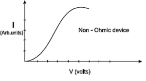
- Several conductors obey the Ohms law. Those materials that obey the law are called ohmic conductors. Metals are the most accurately ohmic conductors. They follow the linear I-V characteristic. The devices for which the I-V curve is not a straight line are called non-ohmic devices. They do not obey the Ohm’s law and the resistance of these devices is a function of V or I.
- Metals obey Ohm’s law only if their physical conditions, such as temperature, remain constant. Their resistance changes with temperature. Hence, their I — V graph deviates from a straight line if the temperature increases due to either prolonged passage of current or passage of a large current. (See below Fig. for reference)
Ohmic conductor: A conductor or a device which obeys Ohm’s law is called an ohmic conductor.
A graph of current (I) versus the potential difference (V) across an ohmic conductor is a straight line through the origin, provided its physical state remains the same, as shown in the following figure :

Hence, the ratio V/I = R, which is the reciprocal of the slope of the straight line, is the same for all values of V. In other words, the resistance of the conductor is independent of the magnitude and polarity of V.
The resistance of a conductor changes with temperature. Hence, the graph is not a straight line when the temperature of the conductor increases due to either prolonged passage of current or passage of a large current.
- Examples : Metals and metallic alloys, e.g., silver, copper, aluminium, iron, manganin, Nichrome, constantan, etc.
Non-ohmic conductor : A conductor or a device which does not obey Ohm’s law is called a non-ohmic conductor.
A graph of current versus potential difference across a non-ohmic conductor is a curve as shown in Fig. for a pn—junction diode (semiconductor diode). That is, the resistance of such a conductor changes with the applied potential difference.
If for a certain potential difference V the current through the conductor is I, then its resistance at that V is given by
R = \(\lim\limits_{ΔI\to 0} \frac{ΔV}{ΔI}=\frac{dV}{dI}\)
where ΔV is the potential difference between the two values of potential V\(-\frac{ΔV}{2}\), V +\(-\frac{ΔV}{2}\) , and ΔI is the corresponding change in the current.
- Examples : Liquid electrolytes, vacuum tubes, junction diodes, thermistors etc.
Electrical Energy and Power :
Power is defined as the time rate of doing work or the time rate of transfer of energy.
Consider a resistor AB connected to a cell in a circuit shown in Fig. with current I flowing from A to B. The cell maintains a potential difference V between the two terminals of the resistor, higher potential at A and lower at B.
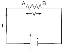
If Q is the charge flowing from A to B in time Δt and W is the work done by the cell in this process, then,
V = W/Q ….(1)
∴ W= VQ …..(2)
This work done by the cell corresponds to the decrease in its potential energy (ΔU).
∴ ΔU = VQ = VIΔt ..(as I = Q/Δt)
By the principle of conservation of energy, this energy is converted into some other forms such as heat and light.
\(\frac{ΔU}{Δt}\) = VI
As Δt → 0, \(\frac{dU}{dt}\) = VI ….(3)
Power, P = time rate of transfer of energy = VI ……(4)
Now, V = RI
∴ P = VI = (RI)I = I2R …..(5)
Also, P = VI = V\(\frac{V}{R}\) = V2/R
Thus, power, P = VI = I2R =\(\frac{V^2}{R}\) ….(7)
Unit : Electrical energy is expressed in joule or watt-hour or kilowatt-hour.
1 kW.h = 3600 J
In electricity bills, kilowatt-hour is simply referred to as the unit.
We reply to valid query.