Notes-Part-1
|
Topics to be Learn : Part-1
|
Introduction :
- Hans Christian Oersted first discovered that magnetic field is produced by an electric current passing through a wire. This phenomenon is known as the magnetic effect of electric current.
- The idea that all magnetic effects can be attributed to moving electric charges was first put forth by Ampere (electric current). A moving electric charge is required to create a magnetic field, and a different moving electric charge is required to experience a magnetic field.
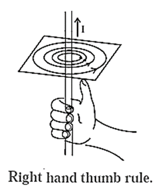
Right hand thumb (grip) rule : The direction of the magnetic induction coincides with the direction of the fingers that are curled around the wire if a straight current-carrying wire is held in the right hand with the thumb extended in the direction of the current.
Expression for the magnetic induction near a straight infinitely long current-carrying wire :
Suppose a point L is at a distance ‘a’ from a straight, infinitely long, wire carrying a current I, as shown in Fig.
It can be shown that the magnitude of the total magnetic induction at P is given by the expression
B = \((\frac{μ_0}{4π})\frac{2I}{a}\)
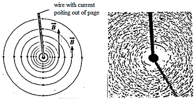
That is, the magnitude B is inversely proportional to the distance from the wire. Because of the axial symmetry about the straight wire, the magnetic induction has the same magnitude B at all points on a circle in a transverse plane and centred on the conductor; the direction of is everywhere tangential to such a circle.
Thus, the magnetic field lines around the current in the straight wire is a family of circles centred on the wire.
The magnitude of the field B depends only on the current and the perpendicular distance ‘a’ of the point from the wire.
Magnetic Force:
Expression for the Lorentz force on a charge due to an electric field as well as a magnetic field :
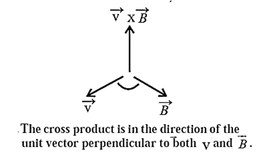
A charge q moving with a velocity through a magnetic field of induction \(\vec{B}\) experiences a magnetic force perpendicular both to \(\vec{B}\) and .\(\vec{v}\)
Experimental observations show that the magnitude of the force is proportional to the magnitude of \(vec{B}\) the speed of the particle, the charge q and the sine of the angle θ between \(\vec{v}\) and \(\vec{B}\). That is, the magnetic force, Fm = qvB sin θ
∴ \(\vec{F_m}\) = q\((\vec{v}×\vec{B})\)
Therefore, at every instant \(vec{F_m}\) acts in a direction perpendicular to the plane of \(\vec{v}\) and \(\vec{B}\).

If the moving charge is negative, the direction of the force \(\vec{F_m}\) acting on it is opposite to that given by the right-handed screw rule for the cross-product \(\vec{v}×\vec{B}\) .
If the charged particle moves through a region of space where both electric and magnetic fields are present, both fields exert forces on the particle.
The force due to the electric field \(\vec{E}\) is \(\vec{F_e}\)= \(q\vec{E}\) .
The total force on a moving charge in electric and magnetic fields is called the Lorentz force :
\(\vec{F}\) =\(\vec{F_e}\)+\(\vec{F_m}\) = \(q(\vec{E}+\vec{v}×\vec{B})\) ……(1)
Special cases :
(i) \(\vec{v}\) is parallel or antiparallel to \(\vec{B}\) : In this case,
Fm = qvB sin 0° = 0. That is, the magnetic force on the charge is zero.
(ii) The charge is stationary (v = 0) : In this case, even if q ≠ 0 and B ≠ 0,
Fm = q(0)B sin θ = 0. That is, the magnetic force on a stationary charge is zero.
From Eq. (1) it may be observed that the force on the charge due to electric field depends on the strength of the electric field and the magnitude of the charge. However, the magnetic force depends on the velocity of the charge and the cross product of the velocity vector the magnetic field vector and the charge q.
Q. Explain why the magnetic force on a charged particle cannot change the linear speed and the kinetic energy of the particle.
Ans.
The magnetic force on a particle carrying a charge q and moving with a velocity \(\vec{v}\) in a magnetic field of induction \(\vec{B}\) is \(\vec{F_m}\)= q\(\vec{v}×\vec{B}\). At every instant, \(\vec{F_m}\) is perpendicular to the linear velocity \(\vec{v}\) and \(\vec{B}\).
Therefore, a non—zero magnetic force may change the direction of the velocity and the dot product .\(\vec{F_m}.\vec{v}\) = \(q(\vec{v}×\vec{B}).\vec{v}\) = 0.
But \(\vec{F_m}.\vec{v}\) is the power, i.e., the time rate of doing work. Hence, the work done by the magnetic force in every short displacement of the particle is zero.
The work done by a force produces a change in kinetic energy. Zero work means no change in kinetic energy. Thus, although the magnetic force changes the direction of the velocity \(\vec{v}\), it cannot change the linear speed and the kinetic energy of the particle.
Unit of magnetic induction from Lorentz force :
If the force F is 1 N acting on the charge of 1 C moving with a speed of 1m s-1 perpendicular to (\vec{B}\) then we can define the unit of B.
B = F/qv , ∴ unit of B is = (N.s)/(C.m) = N/(A.m)
This SI unit of magnetic induction is the tesla (T).
We can define the unit from the velocity-dependent part of the Lorentz force that acts on a charge in motion parallel to a magnetic field.
∴ Definition : The magnitude of magnetic induction is said to be 1 tesla when a charge of 1 coulomb experiences a force of 1 N when it moves at 1 m / s in a magnetic field in a direction perpendicular to the direction of the field.
- 1 T = 104 gauss. Gauss is not an SI unit, but is used as a convenient unit.
Magnetic Resonance Imaging (MRI) :
|
Cyclotron Motion :
In a magnetic field, a charged particle typically undergoes circular motion.
Below figure shows a uniform magnetic field \(\vec{B}\) directed perpendicularly into the plane of the paper (parallel to the -ve z axis).
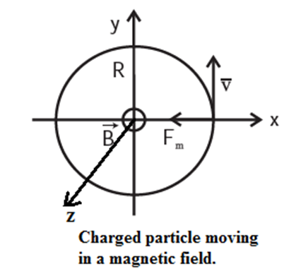
Figure shows a particle with charge q moving with a speed v, and a uniform magnetic field \(\vec{B}\) is directed into the plane of the paper.
According to the Lorentz force law, the magnetic force on the particle will act towards the centre of a circle of radius R, and this force will provide centripetal force to sustain a uniform circular motion.
Thus Fm = qvB = \(\frac{mv^2}{R}\)
∴ mv = p = qBR --- (1)
Equation (1) represents what is known as cyclotron formula. It describes the circular motion of a charged particle in a particle accelerator, the cyclotron.
| Remember : Field penetrating into the paper is represented as ⊗, while that coming out of the paper is shown by ⊕. |
Cyclotron Accelerator:
Cyclotron : A cyclotron is a cyclic magnetic resonance accelerator in which an alternating potential difference of a few kV is used to accelerate light positive ions
such as protons, deuterons, or-particles, etc., but not electrons, to very high energies of the order of a few MeV. It was developed by E. O. Lawrence and M. S.
Livingston in 1932.
Principle : Charged particles that describe a spiral path at right angles to a constant magnetic field and make multiple passes through the same alternating p.d., whose frequency is the same as the frequency of the particles' revolution, are accelerated by the cyclotron using the principle of synchronous acceleration.
Construction of the cyclotron :
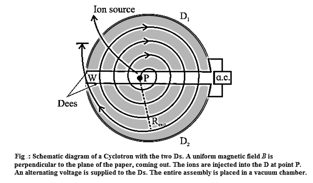
- Two hollow D-shaped chambers that are open at their straight edges form the electrodes. They are called the dees.
- The dees are separated by a small gap, as shown in Fig. and a high—frequency (106 Hz to 107 Hz) alternating p.d. (of the order of 104V to 105 V) is applied between them.
- The whole system is placed in an evacuated chamber between the poles of a large and strong electromagnet (B ≡ 1T to 2T).
- The ions to be accelerated are produced in an ion source; a hydrogen tube gives protons, heavy hydrogen or deuterium gives deuterons while helium gives α-particles, etc.
- The positive ions are injected near the centre and are accelerated each time they cross the gap between the dees.
- At the edge of one of the dees, an electrostatic deflector deflects the spiralling particles out of the system to strike a target.
Working of the cyclotron :
- The dees of the cyclotron are separated by a small gap [See above Fig.] and a high-frequency alternating p.d. is applied between them. Light positive ions are injected into the system near the centre.
- Suppose a positive ion of charge q and mass m is injected when D1 is positive and D2 is negative.
- The positive ion will accelerate towards D2. Inside the dees there is no electric field. Hence, inside D2 it has a constant speed v. The magnetic force of magnitude qvB makes it move in a semicircular path through D2.
- The radius r of its orbit is given by equating the centripetal force to the magnetic force.
- Let t be the time spent by the ion to describe the semicircular path. If t is also half the period of oscillation T of the alternating p.d., the ion will be in resonance with the electric field in the gap. That is, the ion will emerge from D2 at the instant D1 becomes negative and will be accelerated towards D1. As the ion gains speed in the gap, its path in D1 has greater radius.
- This process repeats after every half cycle of the alternating p.d. and the ion is accelerated each time it crosses the gap between the dees.
- The radius of the path of the charged particles increases proportionately with their speed, the period of revolution remains constant.
- After a large number of revolutions, the ion reaches the edge of the system where a negatively charged electrostatic deflector plate deflects it out of the system towards the target.
Functions of the electric and magnetic fields in a cyclotron :
- The magnetic field in the dees of a cyclotron serves to deflect the positively charged particles in semicircular paths so that they return to the gap in a fixed time interval to reuse the alternating electric field.
- The electric field in the gap between the dees of a cyclotron serves to accelerate the positively charged particles.
Cyclotron frequency :
Consider positive ions of charge q and mass m injected in a cyclotron. In the electric-field-free region inside a dee, the ions are acted upon only by the uniform magnetic field. Hence, inside a dee the ions travel in a semicircular path with a constant speed v, in a plane normal to the field.
If B is the induction of the magnetic field, the magnetic force of magnitude qvB provides the centripetal force.
∴ \(\frac{mv^2}{r}\) = qvB
∴ r = \(\frac{mv}{qB}\) ……(1)
Thus, for given q, m and B,
r ∝ v
If t be the time spent in a dee by the ion to describe a semicircular path of radius r,
t = \(\frac{πr}{v}\)= \(\frac{π}{v}×\frac{mv}{qb}\)
∴ t = \(\frac{πm}{qB}\) ……(2)
Thus, t is independent of r and v, i.e., it takes the ions exactly the same time t to travel the semicircular paths inside the dees irrespective of the radius of the path and the speed of the ions so long as the mass m is constant. This is the critical characteristic of operation of the cyclotron.
The periodic time of an ion in its circular path is
T = 2t = \(\frac{2πm}{qB}\) ……(3)
The frequency of revolution,
f = 1/T = \(\frac{qB}{2πm}\) ……(4)
is called the cyclotron frequency or the magnetic resonance frequency.
∴ The frequency is independent of r and v for a given ion species and remains constant so long as the mass m is constant.
The cyclotron frequency depends upon (i) the magnetic induction and (ii) the specific charge (the ratiocharge/mass) of the charged particles.
Maximum ion energy obtainable : If R is the maximum radius of the path, the same as the radius of the dee, just before the ions are deflected out of the accelerator,
vmax = \(\frac{qBR}{m}\) ……(5)
so that KEmax = \(\frac{q^2B^2R^2}{2m}\) (in joule) = \(\frac{q^2B^2R^2}{2em}\) (in eV) ……..(6)
KEmax ∝ R2
Thus, for a given ion species and dees of given radius, final energy is proportional to the square of the radius of the outermost circular path, and
KEmax ∝ B2
Maximum ion energy obtainable is directly proportional to the square of the magnetic induction.
- Therefore the maximum kinetic energy acquired by a charged particle in the cyclotron depends upon (i) the magnetic induction (ii) the specific charge (the ratio charge / mass) of the charged particles and (ii) the radius of the dees.
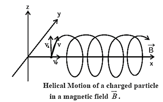
Helical Motion:
Suppose a particle of mass m and charge q starts in a region of uniform magnetic field of induction \(\vec{B}\) with a velocity \(\vec{v}\) which has a non-zero component vll in the direction of \(\vec{B}\) see Fig.
The magnetic force \(\vec{F_m}\) on the particle is always perpendicular to \(\vec{v}\) and provides a centripetal acceleration such that
Fm=|q|v⊥B = \(\frac{mv_{⊥}^{2}}{R}\) ……….(1)
where R is the radius of the circular path.
∴ R = \(\frac{mv_{⊥}}{|q|B}\) ………(2)
The periodic time for one full revolution is
T= (circumference)/(speed) = \(\frac{2πR}{v_⊥}\) = \(\frac{2πmv_⊥}{v_⊥|q|B}\) = \(\frac{2πm}{|q|B}\) …….(3)
The parallel component of the motion \(\vec{v_{||}}\) is unaffected by the magnetic field, so that the motion of the particle is a composite motion : an UCM with speed v⊥—the speed perpendicular to \(\vec{B}\)and a translation with a constant speed v||.
Therefore, the particle moves in a helix (Fig.). Thus, the perpendicular component v⊥ determines the radius of the helix while the parallel component v|| determines the pitch x of the helix, i.e., the distance between adjacent turns. x = v||/T.
Q. State under what conditions will a charged particle moving through a uniform magnetic field travel in (i) a straight line (ii) a circular path (iii) a helical path.
(i) A charged particle travels undeviated through a magnetic field \(\vec{B}\) if its velocity \(\vec{v}\) is parallel or antiparallel to . In this case, the magnetic force on the charge is zero.
(ii) A charged particle travels in a circular path within a magnetic field \(\vec{B}\) if its velocity \(\vec{v}\) is perpendicular to \(\vec{B}\).
(ii) A charged particle travels in a helical path through a magnetic field \(\vec{B}\) if its velocity \(\vec{v}\) is inclined at an angle θ to \(\vec{B}\) , 0 < θ < 90°. In this case, the component of \(\vec{v}\) parallel to \(\vec{B}\) is unaffected by the magnetic field. The radius and pitch of the helix are determined respectively by the perpendicular and parallel components of \(\vec{v}\)
Resonance condition in a cyclotron :
The frequency of the alternating voltage between the dees of a cyclotron should be equal to the cyclotron frequency so that a positive ion exiting a dee always sees an accelerating potential difference to the other dee. This equality of the frequencies is called the resonance condition.
Limitations of a cyclotron :
- Electrons cannot be accelerated using it. Due to their extremely low mass, electrons can accelerate to relativistic speeds, or speeds where their mass increases noticeably as the speed increases. The alternating electric field between the dees prevents them from staying synchronous if that happens.
- For higher energies, with a given magnetic field strength, the exit radius and thus the dees must be large. It is difficult to produce a uniform magnetic field over a large area.
- Even protons, deuterons, on-particles, etc., cannot be accelerated to very high energy, say of the order of 500 MeV, using a cyclotron with a fixed cyclotron frequency.
- No particle accelerator can accelerate uncharged particles, such as neutrons.
Magnetic Force on a Wire Carrying a Current:
Expression for the magnetic force experienced by a straight current-carrying conductor placed in a uniform magnetic field :
Consider a straight current—carrying conductor placed in a region of uniform magnetic field of induction \(\vec{B}\) pointing out of the page, as shown in Fig. by the evenly placed dots. Let the length of the conductor inside the field be l and the current in it be I .
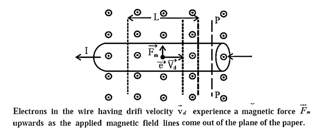
In metallic conductors, electrons are the charge carriers. The direction of conventional current is, however, taken to be that of flow of positive charge which is opposite to the electron current.
Let dq be the positive charge passing through an element of the conductor of length dl in time dt. has the same direction as that of the current.
Then, I = dq/dt ……..(1)
and drift velocity, \(\vec{v_d}\) = \(\vec{dl}/dt\) ……..(2)
The magnetic force on the charge dq is
\(\vec{f_m}\)= \(dq(\vec{v_d}×\vec{B})\) = \(dq(\frac{\vec{dl}}{dt}×\vec{B})\)
= \(I(\vec{dl}×\vec{B})\) .....(.. I = dq/dt)
The charge dq is constrained to remain within the conductor. Hence, the conductor itself experiences this force. The force on the entire part of the conductor within the region of the magnetic field is
\(\vec{F}\) = ∑ \(\vec{f_m}\) = \(I(∑\vec{dl})\) × \(\vec{B}\) = \(I\vec{l} × \vec{B}\)
In magnitude, F = Il B sin θ ………(4)
where θ is the smaller angle between \(\vec{l}\) and \(\vec{B}\)
(i) Expressions for the force experienced by a current-carrying conductor of arbitrary shape:
When the conductor is parallel to the magnetic field, \(\vec{l}\) is parallel or antiparallel to \(\vec{B}\) according as the current is in the direction of \(\vec{B}\) or opposite to it; then θ = 0° or θ = 180°, so that sin θ = 0. Hence, in either of these two cases, F = 0.
(ii) Expressions for the force experienced by a current-carrying closed circuit (conducting loop) :
The maximum value of the force is Fmax = IlB, when sin θ = 1, that is, when the conductor lies at right angles to \(\vec{B}\) (θ = 90°).
(i) For a current-carrying wire of arbitrary shape in a uniform field,
\(\vec{F}\) = \(∫\vec{f_m}\) = \(I(∫\vec{dl})×\vec{B}\) …….(5)
(ii) For a current-carrying conducting loop (closed circuit) in a uniform field,
\(\vec{F}\) = \(∫\vec{f_m}\) = \(I(\oint\vec{dl}×\vec{B})\) …….(6)
But for a closed loop of arbitrary shape, the integral is zero.
∴ \(\vec{F}\) = 0
Torque on a Current Loop:
Explanation : How the magnetic forces on a current loop produce rotary motion as in an electric motor:
Consider a current-carrying rectangular loop ABCD, within a uniform magnetic field see Fig.
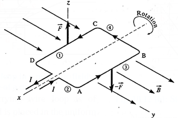
- Lead wires and commutator are not shown for simplicity. The coil is free to rotate about a fixed axis. Suppose the sides AB and CD are perpendicular to the field direction.
- The magnetic force on each segment act at the centre of mass of that segment. The direction of the force on each segment can be found using the right hand rule for the cross product or from Fleming's left hand rule.
- The magnetic forces on the short sides AD and CB are, in general, equal in. magnitude, opposite in direction and have the same line of action along the rotation axis. Hence, these forces cancel out and does not produce any torque.
- The magnetic forces on the long sides AB and CD are also equal in magnitude and opposite in direction but their lines of action are different. Hence, these forces constitute a couple and tend to rotate the coil about the central axis. -
- A commutator (not shown) reverses the direction of the current through the loop every half-revolution so that the torque always acts in the same direction.
Expression for the net torque on a rectangular current-carrying loop placed in a uniform magnetic field with its rotation axis perpendicular to the field :
Consider a rectangular loop ABCD of length l, breadth b and carrying a current I, placed in a uniform magnetic field of induction \(\vec{B}\) with its rotation axis perpendicular to \(\vec{B}\) Fig. (a).
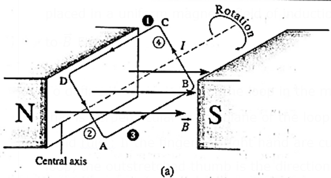
To define the orientation of the loop in the magnetic field, we use a normal vector \(\hat{n}\) that is perpendicular to the plane of the loop. The direction of \(\hat{n}\) is given by a right hand rule : If the fingers of right hand are curled in the direction of current in the loop, the outstretched thumb is the direction of \(\hat{n}\) .
Suppose the normal vector \(\hat{n}\) of the loop makes an arbitrary angle with \(\vec{B}\) as shown in Fig. (b)
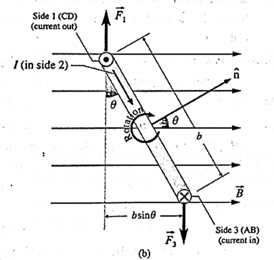
In the side view, Fig. (b), the sides CD, DA, AB and BC have been labelled as 1, 2, 3 and 4, respectively. In this view, the current inside 1 (CD) is out of the page as shown by a Θ while that in side 3 (AB) is into the page shown by a ⊗.
For side 2 (AD) and side 4 (BC), the length of the conductor \(|\vec{L}|\) = b and the angle between \(\vec{L}\) and \(\vec{B}\) is (90°− θ). Hence, the forces on sides 2 and 4 are equal in magnitude :
F2 = F4 = IbB sin(90°− θ) = IbB cos θ
However, \(\vec{F_2}\) is directed out of the page while \(\vec{F_4}\) is into, and because their common line of action is through the centre of the loop, their net torque is zero. For side 1 (CD) and side 3 (AB), \(|\vec{L}|\) = I and \(\vec{L}\) is perpendicular to \(\vec{B}\). Hence, the forces \(\vec{F_1}\) and \(\vec{F_3}\) have the same magnitude : F1 = F3 = Il B
But their lines of action being different, they constitute a couple.
Moment arm of the couple = b sin θ
Torque exerted by the couple = force of the couple x moment arm of couple
∴ τ = (IlB)(b sin θ)
in the clockwise sense in Fig. (b). The torque tends to rotate the loop so as to align its normal vector \(\hat{n}\) with the direction of the magnetic field.
∴ τ = I(lb)B sin θ = IAB sin θ
where A = l b is the area of the loop. For a rectangular coil of N turns in place of a single-turn loop,
τ = NIAB sin θ
This is the required expression for the net torque.
The torque has maximum magnitude for θ =90°, that is when \(\hat{n}\) is perpendicular to \(\vec{B}\) or, in other words, the plane of the coil is parallel to the field.
τmax = NIAB
| Know This:
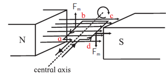
Electric Motor working : In a motor, we require continuous rotation of the current carrying coil. As the plane of the coil tends to become parallel to the magnetic field \(\vec{B}\) the current in the coil is reversed externally.
Referring to Fig. the segment ab occupies the position cd. At this position of rotation, the current is reversed. Instead of from b to a, it flows from a to b, force Fm continues to act in the same direction so that the torque continues to rotate the coil. The reversal of the current is achieved by using a commutator which connects the wires of the power supply to the coil via carbon brush contacts. |
Moving Coil Galvanometer:
Principle : A current-carrying coil suspended in a magnetic field experiences a torque which rotates the plane of the coil and tends to maximize the magnetic flux through the coil.
The deflection of the coil in a moving-coil galvanometer is linearly related to the current through it and, therefore, can be used to measure current in terms of the deflection.
Construction :
Fig. illustrates a permanent fixed-magnet, suspended-type moving-coil galvanometer. It consists of a coil wound on a rectangular, non-conducting, non-magnetic frame with numerous turns of fine, insulated copper wire. A fine phosphor bronze wire F is suspended from an adjustable screw-head between the cylindrically concave pole pieces of a horseshoe permanent magnet to support the coil. A wire helix H that is loosely wound is attached to the coil's other terminal. Between the pole pieces is a cylindrical soft-iron core CS that the coil freely swings around.

The two current leads to the coil are the suspension F and the helix H. When the coil is rotated from its neutral position, the suspension fibre also provides the restoring torque. The soft-iron core and cylindrically concave pole pieces create a radial magnetic field in the annular space where the coil's vertical sides move. Additionally, the annular region experiences increased magnetic induction due to the soft-iron core's concentration of the magnetic field.
The angle of deflection is observed with a beam of light reflected from a small mirror M fixed to the suspension fibre. The reflected beam is observed on a ground-glass scale arranged about a metre from the instrument, the light beam serving as a weight-less pointer.
Working :
Consider a rectangular coil—of length l, breadth b and N turns—carrying a current I suspended in a uniform magnetic field of induction F.
The magnetic forces on the horizontal sides of the coil have the same line of action and do not exert any torque. The magnetic forces on the vertical sides constitute a couple and exert a deflecting torque.
If the plane of the coil is parallel to \(\vec{B}\) the magnitude of the deflecting torque is maximum equal to
τd = NIAB ……(1)
where A = l b is the area of each turn of the coil. This torque rotates the coil.
In a moving-coil galvanometer, the coil swings in a radial magnetic field produced by the combination of the cylindrically concave pole pieces and the soft—iron core.
Here, sin θ = 1 as the field is radial (plane of the coil will always be parallel to the field).

Therefore, the deflecting torque is constant and maximum as given by Eq. (1).
The rotation of the coil twists the suspension fibre which exerts a restoring torque on the coil. The restoring torque is proportional to the angle of twist θ.
τr = Kθ …..(2)
where K is the torque constant, i.e., torque per unit angle of twist. K depends on the dimensions and the elasticity of the suspension fibre.
The coil eventually comes to rest in the position where the restoring torque equals the deflecting torque in magnitude. Therefore, in the equilibrium position,
τr = τd
∴ Kθ = NIAB
∴ θ = \(\frac{NAB}{K}\)
∴ θ ∝ I
Since N, A, B and K are constant. Thus, the deflection of the coil is directly proportional to the current in it.
Q. What will happen if the magnetic field in a moving-coil galvanometer is not radial?
Ans. Suppose the magnetic field is uniform but not radial. Then, when the coil comes to rest after rotation through an angle θ, NIAB cos θ = Kθ (in usual notations).
∴ I ∝ θ/cos θ as N, A, B and K are constants in a particular case.
Thus, the current is not directly proportional to the deflection. Hence, we cannot have a linear scale for measurement.
Advantage of radial magnetic field in a moving-coil galvanometer :
- As the coil rotates, its plane is always parallel to the field. That way, the deflecting torque is always a maximum depending only on the current in the coil, but not on the position of the coil.
- The restoring torque is proportional to the deflection so that a radial field makes the deflection proportional to the current. The instrument then has a linear scale, i.e., the divisions of the scale are evenly spaced. This makes it particularly straight forward to calibrate and to read.
Producing radial magnetic field :
- The pole pieces of the permanent magnet are made cylindrically concave, concentric with the axis of the coil.
- A soft iron cylinder is centred between the pole pieces so that it forms a narrow cylindrical gap in which the sides of the coil can move. Together, they produce a radial magnetic field; that is, the magnetic lines of force in the gap are along radii to the central axis.
Magnetic Dipole Moment:
A current-carrying coil reacts to an external magnetic field in the same way a magnetic dipole does (or a bar magnet). Like a magnetic dipole, a current-carrying coil placed in a magnetic field \(\vec{B}\) experiences a torque. In that sense, the coil is said to be a magnetic dipole.
To account for a torque τ on the coil due to the magnetic field, we assign a magnetic dipole moment \(\vec{μ}\) to the coil, such that
\(\vec{τ}\) = \(\vec{μ}×\vec{B}\) = \(NI\vec{A}×\vec{B}\)
where \(\vec{μ}\) = \(NI\vec{A}\) . Here, N is the number of turns in the coil, I is the current through the coil and A is the area enclosed by each turn of the coil.
The direction of (\vec{μ}\) is that of the area vector (\vec{A}\), given by a right hand rule (see Fig. ) :
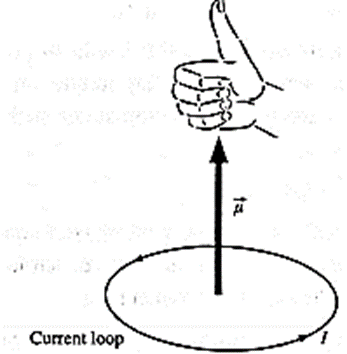
If the fingers of right hand are curled in the direction of current in the loop, the outstretched thumb is the direction of \(\vec{A}\) and \(\vec{μ}\). In magnitude, μ = NIA.
The torque tends to align \(\vec{μ}\) along \(\vec{B}\) .
Magnetic Potential Energy of a Dipole:
Expression for the magnetic potential energy of an magnetic dipole in a uniform magnetic field :
Consider an electric dipole of dipole moment \(\vec{p}\) placed in a uniform electric field \(\vec{E}\) making an angle Φ with \(\vec{E}\). The torque \(\vec{τ}\) = \(\vec{p}×\vec{E}\) tends to rotate the dipole and align it with \(\vec{E}\).
If the dipole was initially parallel to \(\vec{E}\) its potential energy is minimum. We arbitrarily assign U0 = 0 to the minimum potential energy for this position. Then, at a position where \(\vec{p}\) makes an angle θ with \(\vec{E}\) the potential energy of the dipole is
U0 = −pE cos θ = \(-\vec{p}.\vec{E}\)
A current-carrying coil placed in a magnetic field \(\vec{B}\) experiences a torque, \(\vec{τ}\) = \(\vec{μ}×\vec{B}\)
where \(\vec{μ}\) is the magnetic dipole moment of the coil.
In analogy with an electric dipole, the potential energy of a magnetic dipole is e
U0 = −pE cos θ = \(-\vec{μ}.\vec{B}\) ...(2)
U0 is also known as orientation energy.
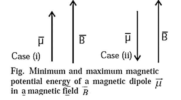
A magnetic dipole has its lowest energy (= −μB cos 0 =−μB ) when its dipole moment is lined up with the magnetic field, and has its highest energy (= −μB cos 180° = +μB) when is directed opposite the field.
We reply to valid query.