Notes-Part-3
Topics to be Learn : Part-3
|
Torque and Couple :
Rotational analogue of a force - moment of a force or torque :
Moment arm or lever arm : The perpendicular distance from the axis of rotation to the line of action of the force is called its moment arm or lever arm.
Explanation :
- While opening a door fixed to a frame on hinges, turning a door requires the least force when it is applied as far away from the rotation axis of the hinges as possible. So, handles on doors are put as far away as possible from the hinges.
- Also, it is easier to turn a door if the force is applied perpendicular to the rotation axis.
- Thus, turning effect of a force or torque depends on the magnitude of the force, its direction and point of application.
- For a measure of the turning effect of a force lying in a plane perpendicular to the axis of rotation, we must consider the magnitude of the applied force and the distance of its line of action from the axis.
Turning effect of a force :
The turning effect of a force is its ability to change the state of rotation of a body. This change may be from rest to motion, from motion to rest or from one speed to another.
- When we push on a door, it turns about a vertical axis through its hinges.
- A wheel can be set into rotation by applying a tangential impulse on its rim. Once set into rotation, its speed of rotation can be increased by an impulse in the same direction as before, or decreased by a frictional force in the opposite direction.
- In each of the cases above, the turning effect of a force causes a change in the rotational state of the body. Changing the direction of the force reverses the effect.
- The turning effect of a force is called the torque. (The use of its old name ’moment of a force’ should be avoided.]
Rigid body:
A rigid body, used as a model of a real object, is a collection of particles such that every particle is at rest relative to all other particles.
- It is assumed that the relative positions of the particles in a rigid body do not change under external forces, i.e., a rigid body cannot be deformed.
- There is really no such object as all objects can be deformed by applying suitable forces and so the concept of a rigid body is an ideal one.
- But many solid objects, such as stones, thick metal rods, etc., are good approximations of a rigid body when forces on them are not very large.
Rotation axis of a rigid body : When a rigid body undergoes rotational motion, its particles move in circles. The centres of all these circles lie on a straight line. This straight line is called the rotation axis of the rigid body.
Torque or moment of a force about a point :
The moment of a force about a point or torque is a quantitative measure of the ability of a force to change the state of rotation of a body. The magnitude of the torque is the product of the magnitude of the force and the moment arm.
Consider a rigid body free to rotate about an axis as shown (Fig). Suppose a force \(\vec{F}\) acts on the body at point P. The position vector of the point of application of the force with respect to the axis is \(\vec{r}\)
The moment arm of the force is the perpendicular distance rL from the axis to the line of action of the force. If θ is the smaller angle between \(\vec{r}\) and \(\vec{F}\), rL = r sin θ.

The magnitude of the torque is τ = FrL = Fr sin θ = rF sin θ
The rotation of a body about a single axis would be clockwise or anticlockwise. The torque is considered positive if it tends to rotate the body anticlockwise, and is negative if it tends to rotate the body clockwise.
In vector form,
\(\vec{τ}\) = \(\vec{r}×\vec{F}\)
The direction of \(\vec{τ}\) is thus given by the right-handed screw rule for a vector product.
SI unit : The newton.metre (N.m).
Dimensions : [τ] = [F] [rL]
= [MLT-2] [L]
= [ML2T-2]
Couple : Two antiparallel forces having equal magnitude but different lines of action acting on a rigid body form a couple.
- Examples : The pair of antiparallel forces applied (1) to turn a tap (2) to work a screw or nut
Expression for the torque due to a couple :
Let a couple consisting of a pair of forces \(\vec{F_1}\) and \(\vec{F_2}\) in the plane of the page act on a rigid body as shown (Fig.); \(\vec{F_2}\) = \(-\vec{F_1}\)
Let F1 = F2 = F. The perpendicular distance rL = AB between their lines of action is called the arm of the couple.
Corresponding position vectors are defined with reference to the lines of action of forces.
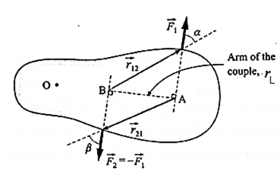
The position vector of any point on the line of action of force \(\vec{F_1}\) from the line of action of force is . Similarly, the position vector of any point on the line of action of force from the line of action of force \(\vec{F_2}\) is \(\vec{r_{12}}\) . Torque or moment of the couple is
\(\vec{τ}\) = \(\vec{r_{12}}×\vec{F_1}\) = \(\vec{r_{21}}×\vec{F_2}\)
From above Fig.
rL = r12 sin α = r21 sin β
Since, in magnitude, F1 = F2 = F
τ = r12F1 sin α = r21F2 sin β = rLF
Thus, the magnitude of the torque due to a couple is equal to the product of the magnitude of one of the forces and the arm of the couple.
The expression for the torque clearly shows that the torque corresponding to a given couple, i.e., the moment of a given couple is constant, i.e., it is independent of the points of application of forces or the position of the axis of rotation, but depends only upon the magnitude of either force and the separation between their lines of action.
To prove that the moment of a couple is independent of the axis of rotation:
Let a couple of a pair of forces \(\vec{F_1}\) and \(\vec{F_2}\) in the plane of the page act on the rigid body as shown (Fig.). \(\vec{F_2}\) = \(-\vec{F_1}\) Let F1 = F2 = F. The perpendicular distance rL = AB is the arm of the couple.
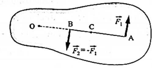
(1) About the point O :
The torque due to \(\vec{F_1}\);
\(\vec{τ_1}\) = \(\vec{OA}×\vec{F_1}\)
∴ τ 1 = F(OA) (anticlockwise)
The torque due to \(\vec{F_2}\) is
\(\vec{τ_2}\) = \(\vec{OB}×\vec{F_2}\)
∴ τ 2 = −F(OB) (clockwise)
Since the torques obey the superposition principle of forces, the resultant torque on the body is the sum \(\vec{τ_1}\) of \(\vec{τ_2}\) and
τ = τ 1 + τ 2 = F(OA) − F(OB)
= F(OA − OB) = F(AB) = FrL (anticlockwise) …..(1)
(2) About the point C :
τ 1 = F(CA) and τ 2 = F(CB) (both anticlockwise)
τ = τ 1 + τ 2 = F(CA) + F(CB)
= F(AB) = FrL (anticlockwise) ……(2)
From Eqs. (1) and (2), the torque due to a couple about any point in its plane is the same, i.e., it is independent of the axis of rotation.
Properties of a couple :
- An unbalanced couple acting on a rigid body changes its state of rotation, i.e., it produces rotational or angular acceleration. Since the resultant of the forces constituting a couple is zero, the body remains in translational equilibrium. Hence, a couple has only a turning effect.
- The magnitude of the torque due to a couple is equal to the product of the magnitude of one of the forces and the arm of the couple.
- The torque due to a couple is a vector along the rotation axis perpendicular to the plane of the couple.
- The torque due to a couple about any rotation axis perpendicular to its plane is the same.
Distinguish between the torques of a force and a couple :
In many situations the word couple is used synonymous to moment of the couple or its torque, i.e., every time we may not say it as torque due to the couple, but say that a couple is acting.
| Torques of a force (Moment of a force ) | Torques of a couple (Moment of a couple) |
| \(\vec{τ}\) = \(\vec{r}×\vec{F}\) | \(\vec{τ}\) = \(\vec{r_{12}}×\vec{F_1}\) = \(\vec{r_{21}}×\vec{F_2}\) |
| \(\vec{τ}\) depends upon the axis of rotation and the point of application of the force. | \(\vec{τ}\) depends only upon the two forces, i.e., it is independent of the axis of rotation or the points of application of forces. |
| It can produce translational acceleration also, if the axis of rotation is not fixed or if friction is not enough. | Does not produce any translational acceleration, but produces only rotational or angular acceleration. |
| Its rotational effect can be balanced by a proper single force or by a proper couple. | Its rotational effect can be balanced only by another couple of equal and opposite torque. |
Mechanical equilibrium:
The momentum of a system is constant in the absence of an external unbalanced force. This state is called mechanical equilibrium.
- A rigid body is said to be in equilibrium if there is no change in its state of motion.
- If there is no change in its velocity, the body is said to be in translational equilibrium.
- If there is no change in the rotational state of the body, it is said to be in rotational equilibrium.
Condition for translational equilibrium:
A rigid body is in translational equilibrium when the resultant force acting on it is zero. By Newton's first law of motion, a body remains in its natural state of constant velocity (including zero) if the net force on the body is zero.
For translational equilibrium, the forces acting on the body must be concurrent. Thus, if F1, F2, F3,.. are concurrent forces acting on a rigid body the first condition of equilibrium is
\(\vec{F_1}+\vec{F_2}+\vec{F_3}\) = 0 or ∑ \(\vec{F_i}\) = 0
Condition for rotational equilibrium : A rigid body is in rotational equilibrium when the resultant torque acting on it is zero. If the forces acting on a rigid body are not concurrent, then their resultant may form a couple. Since the sum of the forces constituting a couple is zero, the first condition for equilibrium is satisfied, But the action of the couple is to change the state of rotation of the body. A body at rest will start rotating, or if it was initially rotating, it will speed up or slow down. Thus, if \(\vec{F_1}\), \(\vec{F_2}\), \(\vec{F_3}\) ,.. are nonconcurrent forces acting on a rigid body and \(\vec{τ_1}\), \(\vec{τ_2}\), \(\vec{τ_3}\), are the respective torques produced by them about any point, the second condition for equilibrium is
\(\vec{τ_1}\) + \(\vec{τ_2}\) + \(\vec{τ_3}\)…. = 0 or ∑ \(\vec{τ_i}\) = 0
Stable, unstable and neutral equilibrium:
Figures (a), (b) and (c) show a ball at rest in three situations under the action of balanced forces.
In all these cases, it is under equilibrium. However, potential energy-wise, the three cases differ.
(i) Stable equilibrium : A body is said to be in a stable equilibrium if, when slightly displaced from its equilibrium position, it returns to its equilibrium position. In this case, the potential energy of the body is at its local minimum.
- Example : A ball placed inside a spherical bowl is in a position of a stable equilibrium, Fig (a).
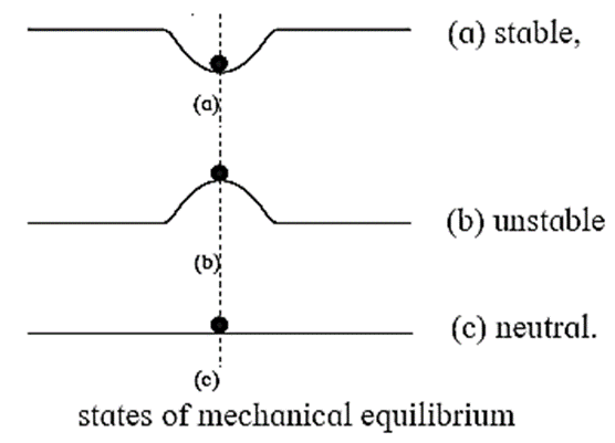
(ii) Unstable equilibrium : A body is said to be in an unstable equilibrium if, when slightly displaced from its equilibrium position, it moves farther from that position. This happens if the body is not initially in a position where its potential energy is not a local minimum. When disturbed, the body moves towards a position of minimum potential energy.
- Example : A ball balanced on the top of an inverted spherical bowl is in a position of a unstable equilibrium, Fig.(b). If it is slightly disturbed from its equilibrium position, it moves farther from that position
(iii) Neutral equilibrium : A body is said to be in an neutral equilibrium if it remains in equilibrium practically at any position. Its potential energy is constant, i.e., not a function of position.
- Example : A ball lying on a flat horizontal surface is in neutral equilibrium, Fig.(c).
Relation between potential energy and stability of a body subjected to a conservative force :
The stability of a system subjected to a conservative force can be understood from the energy diagram which shows the potential energy of the system as a function of position.
The force acting on the system at any position is equal to the negative of the slope of the U(x) versus x curve.
- Positions of stable equilibrium correspond to those values of x for which U(x) has a relative minimum value on an energy diagram.
- Positions of unstable equilibrium correspond to those values of x for which U(x) has a relative maximum value on an energy diagram.
- Neutral equilibrium exists if the potential energy function is constant.
If potential energy function is known for the system, mathematically, the three equilibria can be explained with the help of derivatives of that function. At any equilibrium position, the first derivative of the potential energy function is zero U’(x) = dU/dx = 0
The sign of the second derivative decides the type of equilibrium U’’(x) = d2U/dx2.
- It is positive (U’’(x)>0) at stable equilibrium (or vice versa),
- It is negative (U’’(x)<0) at unstable equilibrium
- It is zero (U’’(x)=0 or does not exist) at neutral equilibrium configuration.
Centre of mass:
Centre of mass : The centre of mass of a system of particles or a rigid body is the point which moves in agreement with Newton's laws of motion as though all the mass of the system is concentrated at this point, and all the external forces act at this point.
Concept of centre of mass (c.m.) helps us in considering finite objects (objects of measurable sizes) to be point objects at a particular location, thereby allowing us to apply Newton’s laws of motion.
Explanation : When a rigid body moves in the presence of external forces, its motion may be pure translation or pure rotation or, in general, a combination of the two.
Consider, for example, a rod is set sliding across a smooth surface with a spin or tossed into the air. In the first case, there is only one point that moves in a straight line with constant velocity; the other points, as they travel, also revolve about the axis through this special point. For the motion under gravity in the second case, again there is only one point that follows the parabolic trajectory, predicted by the equation of motion of the object treated as a particle.
This point for an extended object is the only point associated with the object that moves inan inertial frame in accordance with Newton's laws of motion. It is called the centre of mass‘ Regarding the centre of mass, we can thus make the following statements :
- In the absence of external forces, the centre of mass of a system moves with a constant velocity.
- If a net force \(\vec{F}\) is applied to a system as a whole, the centre of mass undergoes an acceleration \(\vec{a}=\frac{\vec{F}}{M}\), where M is the mass of the system. This is true, regardless of the point of application of the force.
Mathematical understanding of centre of mass:
Expression for the position of the centre of mass of a system of particles :
Consider a system of N particles of masses m1, m2, ..., mN.
Let \(\vec{r_1}\), \(\vec{r_2}\),..... \(\vec{r_N}\) be the respective position vectors of the particles in an inertial frame. The position vector of the centre of mass of the system of particles in that frame is defined as the mass-weighted average position of the system's mass and is
\(\vec{R}=\frac{m_1\vec{r_1}+m_2\vec{r_2}+....m_N\vec{r_N}}{m_1+m_2+...m_N}\)
= \(\frac{1}{M}\sum_{i=1}^{N}m_i\vec{r_i}\)
where M= \(\sum_{i=1}^{N}m_i\) = m1 + m2 +...+ mN is the mass of the system. The rectangular components of \(\vec{R}\) are
X = \(\frac{m_1x_1+m_2x_2+....m_Nx_N}{m_1+m_2+...m_N}\) = \(\frac{1}{M}\sum_{i=1}^{N}m_ix_i\)
and
Y = \(\frac{1}{M}\sum_{i=1}^{N}m_iy_i\), Z = \(\frac{1}{M}\sum_{i=1}^{N}m_iz_i\)
where xi, yi, and zi,- are the components of the position vector \(\vec{r_i}\) of the i th particle of mass mi.
Expression for the centre of mass of a homogeneous rigid body :
Continuous mass distribution: For a continuous mass distribution with uniform density, we need to use integration instead of summation.
Consider a rigid body having a continuous and uniform distribution of mass. Let dm be the mass of an infinitesimal element of the body and be the position vector of the element.
Then, the position vector of the centre of mass of the rigid body is defined as
\(\vec{R}=\frac{\int\vec{r}dm}{\int dm}= \frac{1}{M}\int \vec{r}dm\)
where M =jdm is the total mass of the rigid body. We can write the coordinates of the centre of mass as
X = \(\frac{1}{M}\int xdm\) Y = \(\frac{1}{M}\int ydm\) and Z = \(\frac{1}{M}\int zdm\)
Expressions for the velocity and acceleration of the centre of mass of a system of particles :
Velocity of centre of mass:
Let v1, v2, ... vn be the velocities of a system of point masses m1, m2, ... mn. Velocity of the centre of mass of the system is given by
\(\vec{V}_{cm}=\frac{\sum_{i}^{n}m_i\vec{v_i}}{\sum_{i}^{n}m_i}=\frac{1}{M}\sum_{i}^{n}m_i\vec{v_i}\)
= \frac{\text{resultant of linear momentum}}{\text{linear mass}} = weighted average of momenta
x, y and z components of can be obtained similarly.
For continuous distribution, \(\vec{V}_{cm}= \frac{1}{M}\int \vec{v}dm\)
Acceleration of centre of mass:
Acceleration of the centre of mass of the system is given by
\(\vec{a}_{cm}=\frac{\sum_{i}^{n}m_i\vec{a_i}}{\sum_{i}^{n}m_i}=\frac{1}{M}\sum_{i}^{n}m_i\vec{a_i}\)
where a1, a2, an are the accelerations of the particles of point masses m1, m2, ... mn respectively
x, y and z components of can be obtained similarly.
For continuous distribution, \(\vec{a}_{cm}= \frac{1}{M}\int \vec{a}dm\)
Q. Show that the centre of mass of a system of two particles is (1) closer to the heavier particle (2) midway between the particles of equal mass.
Ans. For a system of two particles, it can be proved that the centre of mass is always on the line joining the two particles and between the two particles. Therefore, we orient the coordinate axes so that the x-axis is along the line joining the two particles and the origin coincides with m1, see below Fig.
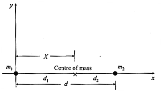
Then, x1 = 0, x2 = d ≡ the separation of the particles, and the x-coordinate of the centre of mass is
X = \(\frac{m_1x_1+m_2x_2}{m_1+m_2}=\frac{m_2}{m_1+m_2}d\) …..(1)
If the particles are at distances d1 and d2 from the centre of mass, then
X = d1 and d = d1 + d2.
Then, from Eq. (1),
(m1 + m2) d1 = m2 (d1 + d2)
∴ m1 d1 = m2 d2
∴ d1/d2 = m2/m1
i.e., the centre of mass divides the line joining the particles in the inverse ratio of their masses.
(1) For unequal masses, say m1 > m2, d1 < d2, and the centre of mass is closer to m1.
(2) If the masses are equal, m1 = m2,
X = d/2 ……[from Eq. (1)] or d1 = d2 ……[from Eq. (2)]
i.e., the centre of mass is midway between the particles.
Characteristics of centre of mass (CM):
- CM is a hypothetical point at which entire mass of the body can be assumed to be concentrated.
- CM is a location, and not a physical quantity.
- CM is particle equivalent of a given object for applying laws of motion.
- CM is the point at which, if a force is applied, it causes only linear acceleration and not angular acceleration.
- CM is located at the centroid, for a rigid body of uniform density.
- CM is located at the geometrical centre, for a symmetric rigid body of uniform density.
- Location of CM can be changed only by an external unbalanced force.
- Internal forces (like during collision or explosion) never change the location of CM.
- Position of the CM depends only upon the distribution of mass, however, to describe its location we may use a coordinate system with a suitable origin. In statistical terms the CM is decided by the weighted average of individual masses. This is obtained by giving proper mass weightage to the distance. This should be clear from the mathematical expression for the location of the CM.
- For a system of particles, the CM need not coincide with any of the particles.
- While balancing an object on a pivot, the line of action of weight must pass through the CM and the pivot. Quite often, this is an unstable equilibrium.
- CM of a system of only two particles divides the distance between the particles in an inverse ratio of their masses, i.e., it is closer to the heavier mass.
- CM is a point about which the summation of moments of masses in the system is zero.
- If there is an axial symmetry for a given object, the CM lies on the axis of symmetry.
- If there are multiple axes of symmetry for a given object, the CM is at their point of intersection.
- CM need not be within the body. e.g., for a body with a curved shape.
- For example, the CM of human body lies within the body, just above the navel; however, at the peak of a Fosbury flop during high jump, the CM lies outside the body below the horizontal bar.
- Other examples include a circular ring, a wire bent into an arc, a doughnut, an L-shaped or U-shaped body.
Coordinates of the centre of mass of the following objects of uniform density :
(1) a thin isosceles triangular plate of height h, with the origin at the centre of the base.
X = 0, Y= h/3
(2) a thin right triangular plate of base p and height q, with the origin at the right-angled vertex.
X = p/3, Y = q/3
(3) a thin semicircular ring of radius R, with the origin at the centre of its diameter.
X = 0, Y= 2R/π
(4) a thin semicircular disc of radius R, with the origin at the centre of its diameter
X = 0, Y= 4R/3π
(5) a hemispherical shell of radius R, with the origin at the centre of its circular base
X = Z = 0, Y= R/2
(6) a solid hemisphere of radius R, with the origin at the centre of its circular base
X = Z = 0, Y= 3R/8
(7) a hollow right circular cone of height h, with the origin at the centre of its circular base.
X = Z = 0, Y= h/3
(8) a solid right circular cone of height h, with the origin at the centre of its circular base.
X = Z = 0, Y= h/4
For a volume of homogeneous matter, the centre of mass is at the centroid of the volume.
| Object | Position of CM |
| Uniform rod | Centre of the rod |
| Circular plate | Centre of the plate |
| Triangular plate | Intersection of medians |
| Rectangular plate | Intersection of diagonals |
| Rectangular block (also cube) | Intersection of the body diagonals |
| Sphere | Centre of the sphere |
| Solid cylinder | Midpoint of its length on the cylinder axis |
Centre of gravity :
Centre of gravity (c.g.) of a body is the point around which the resultant torque due to force of gravity on the body is zero. OR The centre of gravity of a body is a point at which the total downward gravitational force on the body due to the Earth may be considered to act irrespective of its orientation.
Explanation : Consider a rigid body of mass M in a uniform gravitational field. It may be treated as a collection of a large number N of particles of masses m1, m2, ..., mN. In a uniform gravitational field, the acceleration due to gravity \(\vec{g}\) is the same at every point. The gravitational forces on the particles are m1\(\vec{g}\) , m2\(\vec{g}\), …. mN\(\vec{g}\)all parallel, in the direction of
The resultant force on the body
= m1\(\vec{g}\) + m2\(\vec{g}\) +…. mN\(\vec{g}\)
= (m1+m2+...+mN)\(\vec{g}\) = M\(\vec{g}\)
would pass through a point called the centre of gravity ( CG ).
Method of determining the position of the centre of gravity of a lamina of irregular shape :
When a body is freely suspended from a fixed point, its centre of gravity lies vertically below the point of support. This fact is used to find the centre of gravity of a lamina of irregular shape.
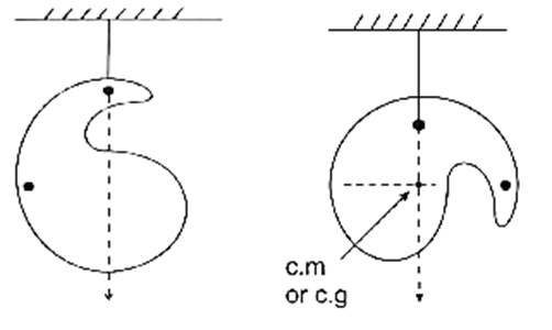
To locate the centre of gravity of a plane lamina of irregular shape, it is freely suspended from a point A, Fig. The vertical line through the point of suspension is marked on the lamina by suspending a plumb line from the same point A. Similarly, the lamina is suspended from another point B, and the vertical line through B is also marked.
The centre of gravity of the lamina is then the intersection of the two vertical lines through the two points of suspension.
We reply to valid query.