Notes-Part-3
Topics to be Learn : Part-3
|
Capacitors and Capacitance, Combination of Capacitors in Series and Parallel:
Resistor : A resistor is an electrical component which allows current to pass through it and dissipates heat but can’t store electrical energy.
Capacitor : A capacitor is a device used to store electrical charge and electrical energy. It consists of at least two electrical conductors, called as capacitor plates, separated by a distance. The space between the plates may simply be air or, usually, filled with a dielectric.
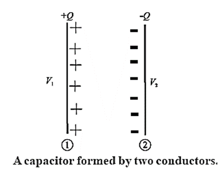
Consider a capacitor having two conducting plates close to, but not touching, one another (Fig). Imagine that each plate is neutral, so the potential difference between the plates is zero.
If a small positive charge q is transferred from one plate to the other, the second plate acquires a charge + q while that on the first plate is —q and a small potential difference appears between the plates.
As the amount of charge on each plate increases, so does the potential difference between the plates.
The potential difference ΔV between the plates is directly proportional to the magnitude of charge Q on each plate :
Q ∝ ΔV
Q = CΔV
The constant of proportionality C is called the capacitance. The capacitance depends only on the geometry of the plates and the type of dielectric between the plates.
When the terminals of a battery are connected to the plates of an initially uncharged capacitor, the battery potential V moves a small amount of charge of magnitude Q from the plate at the higher potential to the other plate. The capacitor remains neutral overall, but with charges + Q and −Q on opposite plates.
The capacitance C is then the ratio of the maximum charge Q that can be stored in the capacitor to the applied voltage V across its plates or, in other words, capacitance is the largest amount of charge per unit potential difference that can be stored on the device.
Capacitance : The capacitance (capacity) of a capacitor is defined as the ratio of the charge on either conductor to the potential difference between the two conductors forming the capacitor.
The SI unit of capacitance is the farad.
The capacitance of a capacitor is said to be one farad if a charge of one coulomb is required to increase the potential difference between the two conductors forming the capacitor by one volt.
1 farad = 1 coulomb/volt; 1 F = 1 C/V
In practice farad is a big unit, the most commonly used units are its submultiples.
- 1μF = 10-6F - microfarad
- 1nF=10-9F - nanofarad
- 1pF = 10-12F -picofarad
Principle of a capacitor: Any conductor can be used to store charges, however, its capacity can be increased by keeping a grounded conductor near it.
To understand the principle of a capacitor let us Consider a metal plate A whose potential is raised to V by depositing a charge + Q on it, so that its capacity is C = Q/V. Now, if an uncharged metal plate B is brought close to plate A, then negative bound charge −Q will be induced on the surface of B near A and positive free charge + Q on the other side of B, see Fig. (a).
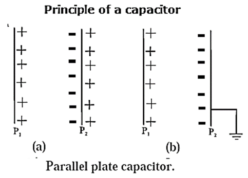
If plate B is grounded, i.e., connected to the Earth, the free charge on it will escape to the Earth, Fig. (b). The bound charge (— Q) thus remaining on B will lower the potential of A, as if superimposing a potential −V1 on the potential V of plate A. The resultant potential of A will become V−V1, and its capacity will be Q/(V − V1).
C’ = Q/(V − V1)
Keeping plate B very close to A, V − V1 can be made very small, so that the capacity of the combination can become very much greater than the capacity of conductor A alone. C’ >> C
Thus capacity of metal plate A, is increased by placing an identical earth connected metal plate B near it.
Such an arrangement is called capacitor. It is symbolically shown as —| |—.
Types of Capacitor :
If the conductors are plane then it is called parallel plate capacitor. We also have spherical capacitor, cylindrical capacitor etc. based on the shape of the conductors.

- Parallel-plate capacitor : It consists of two parallel metal plates, separated by a small gap [Fig.(a)] of air or filled with a dielectric. The charge to be stored is given to one plate (A) while the other plate (B) is earthed.
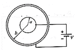
- Spherical capacitor : It consists of two concentric spherical conductors, separated by a small gap of air or filled with a dielectric [Fig.(b)]. The charge to be stored is given to the inner sphere (A), while the outer sphere (B) is earthed.
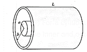
- Cylindrical capacitor : It consists of two coaxial, cylindrical conductors separated by a small gap of air or filled with a dielectric [Fig. (c)]. The charge to be stored is given to the inner cylinder (A), while the outer cylinder (B) is earthed.
Depending on the dielectric used, the capacitors of different types are (i) mica capacitor (ii) air capacitor (iii) paper capacitor (iv) electrolytic capacitor, etc.
Combination of Capacitors:
When there is a combination of capacitors to be used in a circuit, then it can replace with an equivalent capacitor or a single capacitor that has the same capacitance as the actual combination of capacitors.
- The effective capacitance depends on the way the individual capacitors are combined.
- There are two basic combinations of capacitors (i) Capacitors in series and (ii) Capacitors in parallel, which can be replaced by a single equivalent capacitor
(i) Capacitors in series:
When a potential difference (V) is applied across several capacitors connected end to end in such a way that sum of the potential difference across all the capacitors is equal to the applied potential difference V, then the capacitors are said to be connected in series.
In the series arrangement of capacitors, the capacitors are connected end to end and a cell is connected across the combination of the capacitors as shown in below Fig.
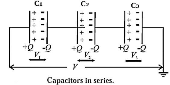
Let C1, C2, C3 be the capacitances of the three capacitors connected in series and Q, the charge on each capacitor. Let V1, V2, V3 be the potential differences across the capacitors.
Now, charge = capacitance x potential difference
Q = C1V1 = C2V2 = C3V3
V1 = Q/C1, V2 = Q/C2, V3 = Q/C3
If V is the potential difference across the combination and C is the equivalent or effective capacitance of the combination, we have,
C = Q/V, ∴ V = Q/C
But V = V1 + V2 + V3
∴ Q/C = Q/C1 + Q/C2 + Q/C3
∴ 1/C = 1/C1 + 1/C2 + 1/C3
In general, if n capacitors of capacitances C1, C2, C3 , ..., Cn are connected in series, the equivalent capacitance (C) of the combination is given by
1/C = 1/C1 + 1/C2 + 1/C3 + …… 1/Cn
Remember :
- Equivalent capacitance is less than the smallest capacitance in series. For several capacitors of given capacitances, the equivalent capacitance of their series combination is minimum.
- All capacitors in the combination have the same charge but their potential differences are in the inverse ratio of their capacitances.
- Series combination of capacitors is sometimes used when a high voltage, which exceeds the breakdown voltage of a single capacitor, is to be divided on more than one capacitors. Capacitive voltage dividers are only useful in AC circuits, since capacitors do not pass DC signals.
(ii) Capacitors in Parallel:
The parallel arrangement of capacitors is as shown in Fig. below, where the insulated plates are connected to a common terminal A which is joined to the source of potential, while the other plates are connected to another common terminal B which is earthed.
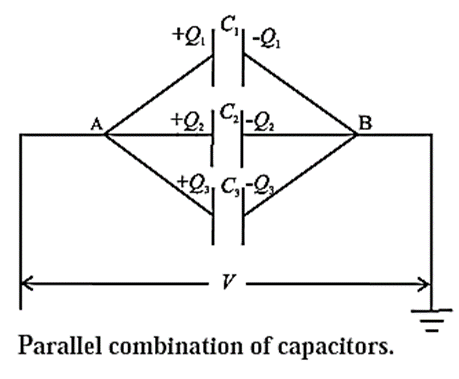
Thus, the potential difference (V) across each capacitor is the same. Let C1, C2, C3 be the capacitances of the three capacitors connected in parallel and C, the equivalent or effective capacitance of the combination. The charge Q supplied by the cell is distributed as Q1, Q2 and Q3 on the capacitors.
Since capacitance = (Charge)/(Potentlal difference)
C1 = Q1/V, C2 = Q2/V, C3 = Q3/V and C = Q/V
Q1 = C1V, Q2 = C2V, Q3 = C3V and Q = CV
Since, Q = Q1 + Q2 + Q3
∴ CV = C1V + C2V + C3V
∴ C = C1 + C2 + C3
In general, if n capacitors are connected in parallel
C = C1 + C2 + C3 ...+Cn
Remember :
- For several capacitors of given capacitances, the equivalent capacitance of their parallel combination is maximum.
- The same voltage is applied to all capacitors in the combination, but the charge stored in the combination is distributed in proportion to their capacitances. The maximum rated voltage of a parallel combination is only as high as the lowest voltage rating of all the capacitors used. That is, if several capacitors rated at 500 V are connected in parallel to a capacitor rated at 100 V, the maximum voltage rating of the capacitor bank is only 100 V.
- Parallel combination of capacitors is used when a large capacitance is required, i.e., a large charge is to be stored, at a small potential difference.
Capacitance of a Parallel Plate Capacitor without and with Dielectric Medium Between the Plates:
Let us now see how the capacitance of a parallel plate capacitor is modified when a dielectric is introduced between its plates.
(a) Capacitance of a parallel plate capacitor without a dielectric (an air or vacuum capacitor) :
Consider a parallel-plate capacitor, consisting of two parallel plates A and B separated by a distance d as shown in Fig.

Let A be the area of each plate. Plate B is connected to the Earth. Suppose that the capacitor is connected to the terminals of a battery of potential difference V. The battery transfers a charge + Q to the insulated plate A. A charge — Q is induced on the near surface of the grounded plate B while the + Q charge on the far side of B flows to the ground.
If the area A is very large and the distance between the plates is very small, the electric field in the region between the plates is almost uniform, except near the edges. The magnitude of the electric field E at a point between the plates and the potential difference V between the plates are related by E = V/d. Outside the capacitors, the electric fields due to the two charged plates cancel out. The net field is zero.
\(\frac{σ}{2ε_0}-\frac{σ}{2ε_0}\) = 0
But, E = \(\frac{σ}{2ε}\), where σ is the surface charge density on the plates.
∴ σ/ε0 = V/d ….(1)
Now σ = Q/A, ∴ E = \(\frac{Q}{ε_0A}\) ….(2)
The capacity (capacitance) of a capacitor is, by definition, C = Q/V
∴ C = \(\frac{ε_0A}{d}\)
This gives the capacitance of a parallel-plate capacitor without a dielectric, i.e., an air or vacuum capacitor.
Remember :
(1) If there are n parallel plates then there will be (n-1) capacitors, hence
C = (n-1)\(\frac{ε_0A}{d}\)
(2) For a spherical capacitor, consisting of two concentric spherical conducting shells with inner and outer radii as a and b respectively, the capacitance C is given by
C = 4πε0\((\frac{ab}{b-a})\)
(3) For a cylindrical capacitor, consisting of two coaxial cylindrical shells with radii of the inner and outer cylinders as a and b, and length ℓ, the capacitance C is given by
C = \(\frac{2πε_0L}{log_e(b/a)}\)
b) Capacitance of a parallel plate capacitor with a dielectric slab between the plates:
Let’s see how Eq. C = \(\frac{ε_0A}{d}\) gets modified with a dielectric slab in between the plates of the capacitor.

Consider a parallel-plate capacitor without a dielectric, of plate area A, plate separation d and capacitance CO, charged to a potential difference V0 and then isolated.
Suppose the charges on its conducting plates are +Q and −Q, Fig. (a). The surface density of free charge is
σ = Q/A ….(1)
If A is very large and d is very small, the electric field in the region between the plates is almost uniform, except near the edges. The magnitude of the electric
field intensity is
E0 = V0/d = σ/ε0 = Q/ε0A ……(2)
Without the dielectric, the capacitance of the parallel plate capacitor is, by definition, C0 = Q/V0 = ……(3)
Now, suppose a dielectric slab of permittivity ε and thickness t (t < d) is introduced in the space between, and parallel to, the charged plates, Fig (b). A polarisation charge −QP appears on the exterior surface of the dielectric nearer to the positive plate while a polarisation charge + QP appears on its opposite face. Since the capacitor was isolated after charging, the free charge Q on the plates is the same as earlier. Within the dielectric, the induced field due to the polarisation charges is opposite to the applied field. The net electric field within the dielectric is less than the applied field. In magnitude, E = E0 − Ep ...(4)
By definition, the relative permittivity (dielectric constant) of the dielectric,
k = ε /ε0 = E/E0 ……..(5)
Between the plates, the field within the dielectric of thickness t is E = E0/k, and that in the region (d − t) is E0. Therefore, the new potential difference between the plates is
V = E0(d − t) + \(\frac{E_0}{k}t\) = E0 (d − t +\(\frac{t}{k}\)) ……(6)
∴ V = \(\frac{V_0}{d}\) (d − t + \(\frac{t}{k}\)) …[from eq-(2)]
Let the capacitance with the dielectric be C. Since the free charge Q remains the same,
C = Q/V = \(\frac{Q}{V_0}\frac{d}{(d-t+\frac{t}{k})}\)
∴ C = C0\(\frac{d}{(d-t+\frac{t}{k})}\) …..(7)
Also from Eqs. (2) and (6),
V = \(\frac{Q}{ε_0A}\)(d − t + \(\frac{t}{k}\))
C = Q/V = \(\frac{ε_0A}{(d-t+\frac{t}{k})}\) …….(8)
Equations (7) and (8) give the capacitance of a capacitor with a dielectric.
Special case :
(i) If the dielectric completely fills the space between the plates, t = d. Therefore, from Eq. (7),
C = C0\(\frac{d}{(d-d+\frac{d}{k})}\) = C0\(\frac{d}{(\frac{d}{k})}\) = kC0
Thus, the capacitance increases by the factor of k.
(ii) If the capacitor is filled with n dielectric slabs of thickness t1, t2....... tn then this arrangement is equivalent to n capacitors connected in series as shown in Fig.
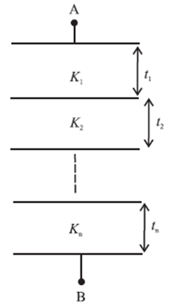
∴ C = \(\frac{ε_0A}{(\frac{t_1}{k_1}+\frac{t_2}{k_2}+...+\frac{t_n}{k_n})}=\frac{ε_0A}{( \sum_{j=1}^{n}\frac{t_j}{j_j})}\)
(iii) If the arrangement consists of n capacitors in parallel with plate areas A1, A2, .............. An and plate separation d
C = \(\frac{ε_0}{d}\)(A1k1 + A2k2 + …… + Ankn)
If A1 = A2 = A3……… = An = A/n
C = \(\frac{ε_0A}{nd}\) (k1 + k2 + …… + kn) =\(\frac{ε_0A}{nd}\)∑j kj
(iv) If the capacitor is filled with a conducting slab (k = ∞) then
C = C0\(\frac{d}{d-t}\) ∴ C > C0
The capacitance thus increases by a factor \(\frac{d}{d-t}\)
Q. Explain how its capacitance of a parallel-plate capacitor can be increased?
The capacitance of a parallel-plate capacitor can be increased by,
- increasing the area of each plate
- decreasing the distance between the two plates
- filling the space between the two plates by a medium of greater relative permittivity.
Functions of a dielectric in a capacitor :
A dielectric material between the plates of a capacitor
- Increases the capacitance of the capacitor
- Provides mechanical support to the plates
- Increases the maximum operating voltage, i.e., the maximum voltage to which the capacitor may be charged without breakdown of the insulating property of the medium between the plates.
Displacement Current:
Consider an uncharged parallel-plate capacitor with capacitance C connected to a resistor R and a battery of voltage V, (see Fig).
For a parallel-plate capacitor, of plate area A, separation d and filled with a dielectric of permittivity ε, its capacitance is
C = εA/d.

When the key is closed, charge begins to flow into the capacitor. The initial voltage across the capacitor is zero and the current in the circuit now is called the charging current.
As the capacitor charges up, the potential difference across its plates slowly increases. During the charging, the charge on the capacitor grows as
Q(t) = Q(1 − e−t/T).
While a capacitor is being charged, there is no current through the capacitor but the electric field between the plates, and the electric flux through a Gaussian surface enclosing one of the plates, increases as the charge on its plates increases. The instantaneous charge on the capacitor is
Q(t) = (εA)E(t) …..[εA = kε0]
∴ \(\frac{d}{dt}\)Q(t) = (εA) \(\frac{d}{dt}\)E(t) = ε\(\frac{d}{dt}\)Φe(t)
where Φe(t) = AE(t) is the electric flux through the surface. The rate of change of charge, \(\frac{d}{dt}\)Q(t), has the dimension of current and is the conduction current ic.
The fictitious current arising from the changing electric flux is called the displacement current : id = ε\(\frac{d}{dt}\)Φe(t)
That is, we imagine the changing flux through the dielectric is somehow equivalent to the conduction current in the circuit.
This lets us generalize Kirchhoff’s junction rule : considering the top plate of the capacitor in the figure, when we include the displacement current, we see that the conduction current coming in from top and an equal displacement current coming out of the bottom. With this generalized meaning of the term "current", we speak of current going through the capacitor.
Maxwell introduced the concept of displacement current to generalize Ampére's law in his formulation of electromagnetic theory that led to the discovery of electromagnetic waves.
Remeber :
- The lowercase i is used to denote instantaneous value of current.
- The actual time taken for the charge on the capacitor to reach 63% of its maximum possible voltage is known as one time constant (T = RC).
- For all practical purposes, a capacitor is considered to be fully charged to Q after a time t= 5T.
Energy Stored in a Capacitor:
A capacitor is a device used to store energy. Charging a capacitor means transferring electron from one plate of the capacitor to the other.
To charge a capacitor, an external agent has to do work against the electrostatic forces due to the charges already present on the plates of the capacitor.
Let C be the capacitance of the capacitor. Let Q and V be the final charge and the potential difference respectively when the capacitor is charged.
Let q be the charge on the capacitor at some stage during the charging and v, the corresponding potential difference between the plates.
The work done by an external agent in bringing additional small charge dq from infinity and depositing it on the capacitor is
dW = potential difference x charge = v dq
But C = q/v ∴ v = q/C
∴ dW =\(\frac{q}{c}dq\)
The total work done in charging the capacitor is
W = \(\int dW=\int_{0}^{Q}\frac{qdq}{C}=\frac{1}{c}[\frac{q^3}{2}]_0^Q=\frac{1}{2}\frac{Q^2}{C}\)
Now Q = CV
∴ W = \(\frac{1}{2}\) CV2 = \(\frac{1}{2}\)(CV)V = \(\frac{1}{2}\)QV
This work is stored in the form of potential energy, in the electric field in the medium between the plates of the capacitor.
∴ Energy of a charged capacitor = \(\frac{1}{2}\frac{Q^2}{C}\) = \(\frac{1}{2}\)CV2 = QV
Q. How does the energy stored in a charged capacitor change if the plates of the capacitor are moved farther apart (i) after the battery is disconnected (ii) the battery remaining connected?
(i) If the plates of a charged capacitor are moved farther apart after the battery is disconnected, the energy stored increases by the amount of work done by the external agent in pulling the plates apart against the force of attraction between the opposite charges on the plates. (ii) With the battery still connected, increasing the separation between the plates decreases the energy stored in the charged capacitor.
Remember :
- The maximum capacitance of four identical capacitors, each of capacitance C, is obtained for their parallel combination : Cp = 4C.
- Their series combination has the minimum capacitance.
- The charge stored in their parallel combination is four times that in their series combination.
- For the same constant p.d. V, the energy stored in the parallel combination is ½(4Q)V and that in the series combination is ½ QV.
- Thus, the series combination will store minimum energy.
Van de Graaff Generator:
Van de Graaff generator is a device used to develop very high potentials of the order of 107 volts. It was designed by Van de Graaff in the year 1931.
The resulting large electric fields are used to accelerate charged particles (electrons, protons, ions) to high energies needed for experiments to probe the small scale structure of matter and for various experiments in Nuclear Physics.
Principle of working : This generator is based on
- The phenomenon of Corona Discharge (action of sharp points),
- The property that charge given to a hollow conductor is transferred to its outer surface and is distributed uniformly over it,
- If a charge is continuously supplied to an insulated metallic conductor, the potential of the conductor goes on increasing.
Construction : Refer below Fig. Working : Refer above Fig.

Uses: The main use of Van de Graff generator is to produce very high energy charged particles having energies of the order of 10 MeV. Such high energy particles are used
- To carry out the disintegration of nuclei of different elements,
- To produce radioactive isotopes,
- To study the nuclear structure,
- To study different types of nuclear reactions,
- Accelerating electrons to sterilize food and to process materials.
- X ray therapy.
We reply to valid query.