Notes-Part-2
Topics to be Learn : Part-2
|
Magnetic Field due to a Current : Biot-Savart Law:
Consider a very short segment of length dl of a wire carrying a current I. The product \(I\vec{dl}\) is called a current element; the direction of the vector \(\vec{dl}\) is along the wire in the direction of the current.
Biot-Savart law (Laplace law) : The magnitude of the incremental magnetic induction \(\vec{dB}\) produced by a current element I at a distance r from it is directly proportional to the magnitude Idl of the current element, the sine of the angle between the current element \(I\vec{dl}\) and the unit vector \(\hat{r}\) directed from the current element toward the point in question, and inversely proportional to the square of the distance of the point from the current element; the magnetic induction is directed perpendicular to both \(I\vec{dl}\) and \(\hat{r}\) as per the cross product rule.

dB ∝ \(\frac{Idlsinθ}{r^2}\)
∴ dB = \(\frac{μ_0}{4π}\,\frac{Idlsinθ}{r^2}\) ….(1)
In vector form \(\vec{dB}\) = \((\frac{μ_0}{4π})\frac{I\vec{dl}×\hat{r}}{r^2}\) ….(2)
Where \(\hat{r}=\frac{\vec{r}}{r}\) and the constant μ0 is the permeability of free space. Equations (1) and (2) are called Biot-Savart law.
The incremental magnetic induction \(\vec{dB}\) is given by the right-handed screw rule of vector cross-product \(\frac{I\vec{dl}×\hat{r}}{r^2}\) .
In Fig., the current element \(I\vec{dl}\) and \(\hat{r}\) are in the plane of the page, so that \(d\vec{B}\) points out of the page at point P shown by Θ at the point Q, \(\vec{dB}\) points into the page shown by ⊗
The magnetic induction \(\vec{dB}\) at the point due to the entire wire is, by the principle of superposition, the vector sum of the contributions \(d\vec{B}\) from all the current elements making up the wire.
From Eq. (2),
\(\vec{B}\) = \(∫\vec{dB}\) = \(\frac{μ_0}{4π}∫\frac{I\vec{dl}×\hat{r}}{r^2}\)
Current in a straight, long wire:
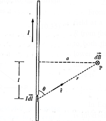
Expression for the magnetic induction near a straight infinitely long current-carrying wire : Suppose a point P is at a distance a from a straight, infinitely long, wire carrying a current I, as shown in below Fig. The incremental magnetic induction \(\vec{dB}\) at the point P due to a current element, \(I\vec{dl}\) is \(\vec{dB}\) = \((\frac{μ_0}{4π})\frac{I\vec{dl}×\hat{r}}{r^2}\)….(1) In magnitude, dB = \((\frac{μ_0}{4π})\frac{Idlsinθ}{r^2}\) ….(2) At the point P, \(\vec{dB}\) is directed perpendicular to the plane of the figure and into of the page as given by the right hand rule for the direction of \(\vec{dl}×\hat{r}\) At point P, \(\vec{dB}\) has this same direction for all the current elements into which the wire can be divided. Thus, we can find the magnitude of the magnetic field produced at P by the current elements in the lower half of the infinitely long wire by integrating dB in Eq. (2), from 0 to ∞. Now consider a current element in the upper half of the wire, one that is as far above P as \(I\vec{dl}\) is below P. By symmetry, the magnetic field produced at P by this current element has the same magnitude and direction as that from \(I\vec{dl}\) in Fig. Thus, the magnetic field produced by the upper half of the wire is exactly the same as that produced by the lower half. Hence, the magnitude of the total magnetic field at P is B = \(\int_{-∞}^{∞}dB\) = \(2\int_{0}^{∞}dB\) = \(2\frac{μ_0I}{4π}\int_{0}^{∞}\frac{dlsinθ}{r^2}\) …..(3) From fig r = \(\sqrt{l^2+a^2}\) ∴ sin θ = \(\frac ar \) = \(\frac{a}{\sqrt{l^2+a^2}}\) ∴ B = \(2\frac{μ_0I}{4π}\int_{0}^{∞}\frac{dl}{(l^2+a^2)}\frac{a}{\sqrt{l^2+a^2}}\) = \(\frac{μ_0aI}{2π}\int_{0}^{∞}\frac{dl}{(l^2+a^2)^{3/2}}\) …..(4) = \(2\frac{μ_0aI}{4π}×\frac{1}{a^2}[\frac{l}{(l^2+a^2)^{1/2}}]_{i=0}^{i=∞}\) = \(\frac{μ_0}{4π}\frac{2I}{a}[1-0]\)=\(\frac{μ_0}{4π}\frac{2I}{a}\) …..(5) That is, the magnitude B is inversely proportional to the distance from the wire. Because of the axial symmetry about the straight wire, the magnetic induction has the same magnitude B at all points on a circle in a transverse plane and centred on the conductor; the direction of \(\vec{B}\) is everywhere tangential to such a circle. Thus, the magnetic field lines around the current in the straight wire is a family of circles centred on the wire.
Expression for the force per unit length between two infinitely long parallel conductors carrying current and hence define the ampere : When two currents pass in adjacent parallel straight conductors, we may think of each of the currents as being situated in the magnetic field caused by the other current. This results in a force on each conductor. Consider two infinitely long, straight parallel wires, each of length l a distance s apart in vacuum, as shown in Fig. (a). The magnetic field around the wire 1, carrying a current I1 has an induction of magnitude B1 = \((\frac{μ_0}{4π})\frac{2I_1}{s}\) Wire 2, with a current I2 in the same direction as I1, is situated in this field. The direction of the field with induction \(\vec{B_1}\) at the position of wire 2, given by the right hand [grip] rule, is perpendicular to the plane of the two conductors, as shown. Hence, the force \(\vec{F_2}\) on wire 2 has a magnitude. F2 = I2 l B1 = \((\frac{μ_0}{4π})\frac{2I_1I_2l}{s}\) …..(1) and is, by Fleming's left hand rule, towards wire 1. Similarly, the magnetic induction \(\vec{B_2}\) at the position of wire 1 has a magnitude B2 = \((\frac{μ_0}{4π})\frac{2I_2}{s}\) and is also directed perpendicular to the plane of the wires. Hence, the force on wire 1 has a magnitude F1 = I1lB2 = \((\frac{μ_0}{4π})\frac{2I_1I_2l}{s}\) …..(2) directed towards wire 2. Thus, the two currents attract each other. \(\vec{F_1}\) = \(-\vec{F_2}\) i.e., they are equal in magnitude and opposite in direction. Ampere found that the wires attracted each other when the currents in them were in the same direction [Fig. (a)], and repelled each other when they were in the opposite directions [Fig. (b)]. From the Eq. (2), the force per unit length acting on each wire is \(\frac{F}{l}\) = \((\frac{μ_0}{4π})\frac{2I_1I_2}{s}\) Using SI units, μ0/4π = 10−7 N/A2 and, if I1 =I2 = 1 A and s = 1m, then \(\frac{F}{l}\) = 2 x 10⁻⁷ N/m In SI, this equation is the defining relation for the ampere.

Ampere : The ampere is that constant current which if maintained in two infinitely long, straight parallel wires, and placed one metre apart in vacuum, would cause each conductor to experience a force per unit length of 2 x 10⁻⁷ newton per metre.
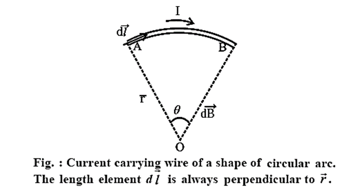
Magnetic Field Produced by a Current in a Circular Arc of a Wire: Below figure depicts a circular arc of a wire (AB), carrying a current I. First obtain the magnetic field produced by one current-length element of the arc and then integrate over the entire arc length. The circular arc AB subtends an angle θ at the centre O of the circle of which the arc is a part, and r is its radius. The unit vector \(\hat{r}\) from each current element \(I\vec{dl}\) towards the centre of the loop is perpendicular to \(I\vec{dl}\), i.e., the angle between them is 90°. Since every current element is equidistant from the centre of curvature O, the magnetic field at O due to each current element in the arc by Biot-Savart’s law is \(\vec{dB}\) = \((\frac{μ_0}{4π})\frac{I\vec{dl}×\hat{r}}{r^2}\) ……(1) dB = \((\frac{μ_0}{4π})\frac{Idl\,sin90^0}{r^2}\)= \((\frac{μ_0}{4π})\frac{Idl}{r^2}\) ……(2) Equation (2) gives the magnitude of the field. The direction of the field is given by the right hand rule. Aligning the thumb in the direction of the current, the field direction is indicated by the curling fingers. Thus, the direction of each of the dB is into the plane of the paper. The total field at O is therefore, B = ∫dB = \(\frac{μ_0}{4π}I\int_{A}^{B}\frac{dl}{r^2}\) = \(\frac{μ_0}{4π}I\int_{0}^{θ}\frac{r}{r^2}dθ\) = \(\frac{μ_0}{4π}\frac{Iθ}{r}\)…..(3) where the angle θ is in radians.
Magnetic field at the centre of a full circle of a wire, carrying a current I :
For a full circular wire carrying a current I, the magnetic field at the centre of the circle, using Eq. (3),
B = \(\frac{μ_0}{4π}\frac{I}{r}2π\) = \(\frac{μ_0I}{2r}\) …. (4)
If a circular coil has N turns, each of radius r and carries a current I, the magnetic induction at its centre has a magnitude
B = \(\frac{μ_0NI}{2r}\) …. (5)
Axial Magnetic Field Produced by Current in a Circular Loop:
Consider a circular, conducting loop of radius R in the xy-plane, whose centre is at the origin. For any point P on the z-axis (which is also the axis of the loop), the current element \(I\vec{dl}\) is perpendicular to the unit vector \(\hat{r}\) directed from the current element to point P.

The incremental magnetic induction, \(\vec{dB}\), due to a current element at Q lies in the plane QOP, in the direction of \(I\vec{dl}\)×\(\vec{r}\) as shown in belowFig.
In magnitude,
dB = \((\frac{μ_0}{4π})\frac{Idl\,sinθ}{r^2}\) = \((\frac{μ_0}{4π})\frac{Idl}{r^2}\)
where we have substituted θ = 90°, \(I\vec{dl}\) being perpendicular to (\hat{r}\).
Each element of the loop has its diametrically opposed companion \(I\vec{dl}\) on the other-side of the loop, both of equal segment length dl.
Point P is equidistant from the two elements, that is, r = r’.
Therefore, the two contributions \(\vec{dB}\) and \(\vec{dB}'\) have equal magnitudes, and their vertical components, dB cos α and dB’cos α, are oppositely directed. Thus, they will add to zero when all the \(\vec{dB}\) contributions are summed, and there can be no vertical component of the resultant induction \(\vec{B}\). However, the horizontal components are of like direction and will sum to a definite value and hence \(\vec{B}\) will have only a horizontal z-component. For the magnitude of \(\vec{B}\), we need to add only the z-components of the \(\vec{B}\) vectors :
B = ∑ dB sin α
∴ B = \((\frac{μ_0}{4π})\frac{I\,sinα}{r^2}\) ∑ dl
= \((\frac{μ_0}{4π})\frac{I\,sinα}{r^2}(2πR)\)
= \((\frac{μ_0}{4π})\frac{2πIR}{r^2}(sinα)\)
From the figure, r2 = R2 + Z2 and sin α = R/r’
so that we have
B = \((\frac{μ_0}{4π})\frac{2πIR}{(R^2+z^2)}·\frac{R}{\sqrt{R^2+z^2}}\)
= \((\frac{μ_0}{4π})\frac{2πIR^2}{(R^2+z^2)^{3/2}}\)
Since πR2 is the area A of the coil,
B = \((\frac{μ_0}{4π})\frac{2IA}{(R^2+z^2)^{3/2}}\) ……(1)
For values of z that are much larger than the radius R, we may ignore the value of R in the denominator above and write
B = \((\frac{μ_0}{4π})\frac{2IA}{z^3}\) ......(for z >> R) ……(2)
For a circular coil of N turns Eqs. (1) and (2) are, respectively,
B = \((\frac{μ_0}{4π})\frac{2NIA}{(R^2+z^2)^{3/2}}\) and B = \((\frac{μ_0}{4π})\frac{2NIA}{z^3}\)
Know This :
|
Magnetic Lines for a Current Loop:
Q. How is the magnetic field of a small current loop identical to that of a short magnetic dipole ? Explain.
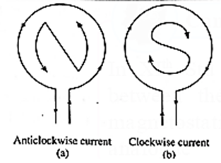
An electric current in a circular loop establishes a magnetic field similar in every respect to the field of a magnetic dipole (or a bar magnet). Consider a circular conducting loop of radius R, axis along the x-axis and carrying a current I. The area of the loop is A = πR2 and \(\vec{A}\) has the direction given by right hand rule. The axial magnetic induction of the current loop at a distance x from its centre is \(\vec{B}\) = \((\frac{μ_0}{4π})\frac{2I\vec{A}}{(R^2+z^2)^{3/2}}\) = \((\frac{μ_0}{4π})\frac{2\vec{μ}}{(R^2+z^2)^{3/2}}\) where \(\vec{M}\)= \(I\vec{A}\) is the magnetic moment of the current loop and μ0 is the permeability of free space. For x >> R, ignoring R2 in comparison with x2, \(\vec{B}\) = \((\frac{μ_0}{4π})\frac{2\vec{μ}}{x^3}\) This equation also gives the magnetic induction on the axis of a short magnetic dipole (or a bar magnet) of magnetic moment \(\vec{μ}\) For a magnetic dipole, the dipole moment is directed from the south pole of the dipole to its north pole. For a current loop, the magnetic dipole moment has the direction of the axial field of the current loop as given by the right-hand rule. When an observer looking at a current carrying circular loop finds the direction of the current anticlockwise, the face of the loop towards the observer acts as the north-pole. When an observer looking at a current-carrying circular loop finds the direction of the current clockwise, the face of the loop towards the observer acts as the south- pole. This rule is known as the clock rule.

Expressions for the axial fields of an electric dipole and a small current-loop :
The axial far field of an electric dipole of electric dipole moment \(\vec{p}\) at an axial point r is
\(\vec{E}\) = \(\frac{1}{4πε_0}\frac{2\vec{p}}{r^3}\)
The axial magnetic field far from a small current-loop is
\(\vec{B}\) = \((\frac{μ_0}{4π})\frac{2\vec{μ}}{x^3}\)
where \(\vec{μ}\) = \(I\vec{A}\) is the magnetic dipole moment of the loop, I is the current in the loop and \(\vec{A}\) is the area vector given by the right-hand rule. The axial field of an electric dipole, \(\vec{E}\) is in the direction of the dipole moment \(\vec{p}\). On the axis of a current loop, the magnetic field \(\vec{B}\) is in the direction of the dipole moment \(\vec{μ}\).
Ampere's Law:
Ampére’s circuital law : In free space, the line integral of magnetic induction around a closed path in a magnetic field is equal to μ0 times the net steady current enclosed by the path.
In mathematical form,
\(\oint \vec{B}.\vec{dl}\) = μ0 I
where \(\vec{B}\) is the magnetic induction at any point on the path in vacuum \(\vec{dl}\) is the length element of the path, I is the net steady current enclosed and μ0 is the permeability of free space.
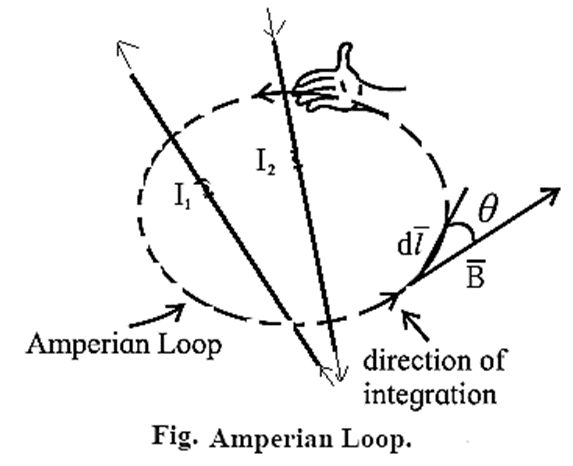
Explanation : Figure shows two wires carrying currents I1 and I2 in vacuum. The magnetic induction \(\vec{B}\) at any point is the net effect of these currents. To find the magnitude B of the magnetic induction: For each length element of the Ampérian loop, \(\vec{B}.\vec{dl}\) gives the product of the length dl of the element and the component of \(\vec{B}\) parallel to \(\vec{dl}\). If θ is the angle between \(\vec{dl}\) and \(\vec{B}\), \(\vec{B}.\vec{dl}\) = (B cos θ) dl Then, the line integral, \(\oint \vec{B}.\vec{dl}\) = \(\oint B\, cos θ\, dl\) For the case shown in above Fig. the net current I through the surface bounded by the loop is I = I2 − I1 ∴ \(\oint B\,cos θ\, dl\) = μ0I = μ0 (I2 − I1) …….(3) Equation (3) can be solved only when B is uniform and hence can be taken out of the integral. Remeber : Ampére's law in magnetostatics plays the part of Gauss's law of electrostatics. In particular, for currents with appropriate symmetry, Ampére’s law in integral form offers an efficient way of calculating the magnetic field. Like Gauss’s law, Ampere’s law is always true (for steady currents), but it is useful only when the symmetry of the problem enables B to be taken out of the integral \(\oint B\, cos θ\, dl\). The current configurations that can be handled by Ampére’s law are infinite straight conductor, infinite plane, infinite solenoid and toroid.
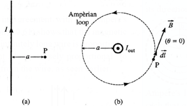
Expression for the magnetic induction near a current-carrying straight, infinitely long wire. Consider a point P at a distance a from a straight, infinitely long wire carrying a current I in free space, see Fig. (a). Because of the axial symmetry about the straight wire, the magnetic induction has the same magnitude B at all points on a circle in a transverse plane and centred on the wire. We, therefore, choose an Ampérian loop a circle of radius a centred on the wire with its plane perpendicular to the wire, as shown in above Fig. (b). \(\vec{B}\) is everywhere tangential to the circular Ampérian loop. Therefore, the angle θ between \(\vec{B}\) and a length element \(\vec{dl}\) is zero at all points of the loop. ∴ \(\oint \vec{B}.\vec{dl}\) = \(\oint B\,dl\,cos θ\) = \(B\oint dl\) = B(2πa) since cos θ = 1 and B has the same value around the path. \(\oint dl\) gives the circumference of the circular loop. In the figure, the Amperian loop is traced in the anticlockwise sense, so that the current I is taken as positive in accordance with the right hand rule. By Ampére’s law, \(\oint \vec{B}.\vec{dl}\) = μ0I ∴ B(2πa) = μ0I ∴ B = \(\frac{μ_0I}{2πa}\) This is the required expression. .
Magnetic Field of a Solenoid and a Toroid:
Solenoid: A solenoid is a long wire that has been wound into a helix shape. The
perfect solenoid has tightly spaced turns and is infinitely long, meaning that it is much longer than its cross-sectional radius.

- Each turn of a solenoid acts approximately as a circular loop. Suppose the solenoid carries a steady current I. The net magnetic field due to the current in the solenoid is the vector sum of the fields due to the current in all the turns.
- In the case of a tightly wound solenoid of finite length, (see Fig.) the magnetic field lines are approximately parallel only near the centre of the solenoid, indicating a nearly uniform field there. However, close to the ends, the field lines diverge from one end and converge at the other end.
- This field distribution is similar to that of a bar magnet. Thus, one end of the solenoid behaves like the north pole of a magnet and the opposite end behaves like the south pole. The field outside is very weak near the midpoint.
For an ideal solenoid, the magnetic field inside is reasonably uniform over the cross section and parallel to the axis throughout the volume enclosed by the solenoid. The field outside is negligible in this case.
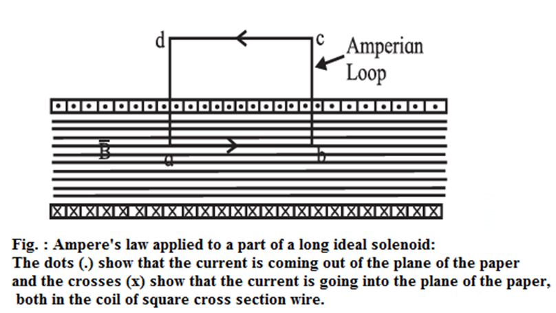
Expression for the magnetic induction inside an ideal solenoid carrying a steady current : An ideal solenoid is tightly wound and infinitely long. Let n be the number of turns of wire per unit length and I be the steady current in the solenoid. For an ideal solenoid, the magnetic induction inside is reasonably uniform over the cross section and parallel to the axis throughout the volume enclosed by the solenoid; \(\vec{B}\) outside is negligible. As an Ampérian loop, we choose a rectangular path abcd of length l parallel to the solenoid axis, Fig. The width of the rectangle is taken to be sufficiently large so that the side dc is far from the solenoid where \(\vec{B}\) = 0. The line integral of the magnetic induction around the Amperian loop in the sense abcda is \(\oint \vec{B}.\vec{dl}\) = \(\oint_{a}^{b} \vec{B}.\vec{dl} + \oint_{b}^{c} \vec{B}.\vec{dl} + \oint_{c}^{d} \vec{B}.\vec{dl} + \oint_{d}^{a} \vec{B}.\vec{dl}\) ……(1) \(\vec{B}\) is constant inside and is parallel to side ab. Hence, as we go in the same direction as \(\vec{B}\) from a to b, \(\vec{B}\) and \(\vec{dl}\) are parallel so that \(\oint_{a}^{b} \vec{B}.\vec{dl}\) = \(\oint_{a}^{b} Bdl\) = \(B\oint_{a}^{b} dl\) = \(Bl \) ……(2) Along the paths c → d and d → a, \(\vec{B}\) is perpendicular to \(\vec{dl}\) inside the solenoid while \(\vec{B}\) = 0 outside. ∴ \(\oint_{b}^{c} \vec{B}.\vec{dl}\) = \(\oint_{d}^{a} \vec{B}.\vec{dl}\) = 0 ……(3) Also \(\vec{B}\) = 0 along side cd, so that \(\oint_{c}^{d} \vec{B}.\vec{dl}\) = 0 ……(4) Thus, from Eqs. (1), (2), (3) and (4), \(\oint \vec{B}.\vec{dl}\) = \(Bl \) ……(5) The total current enclosed by the Amperian loop is Iend = current through each turn x number of turns enclosed by the loop = I x nl = nl I ……(6) By Ampere’s law, \(\oint \vec{B}.\vec{dl}\) = μ0 Iend (in vacuum) Therefore, from Eq.s (5) and (6), Bl = μ0 nl I ∴ B = μ0 nI ….(7) This is the required expression. Remember :
Q. What is the magnetic field (i) outside (ii) inside a long air-cored current-carrying solenoid?
For an ideal solenoid, the magnetic field induction outside is negligible, nearly zero. Inside the solenoid, the field lines are parallel to the axis of the solenoid and the magnitude of the magnetic induction, B = μ0 nI , where μ0 is the permeability of free space, n is the number of turns of wire per unit length and I is the steady current in the solenoid.
Toroid: A toroid is a solenoid of finite length bent into a hollow circular tube like structure similar to a pressurized rubber tube inside a tyre of vehicle. Schematic of a cross section of a toroid is shown in Fig.
An ideal toroid consists of a long conducting wire wound tightly around a torus, a doughnut-shaped ring, made of a non-conducting material.
In an ideal toroid carrying a steady current, the magnetic field in the interior of the toroid is tangential to any circle concentric with the axis of the toroid and has the same value on this circle. Also, the magnitude of the magnetic induction external to the toroid is negligible.
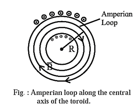
Expression for the magnetic induction inside an ideal toroid carrying a steady current : An ideal toroid consists of a long conducting wire wound tightly around a torus made of a nonconducting material. When a steady current is passed through it, the magnetic induction in the interior of the toroid is tangent to any circle concentric with the axis of the toroid and has the same value on this circle. Suppose the toroid has N turns of wire and I is the current in its coil. As our Ampérian loop, we choose a circle of radius r concentric with the axis of the toroid, as shown in Fig. Since \(\vec{B}\) has the same value on this circle and is tangential to it, we go around this path in the direction of \(\vec{B}\) so that \(\vec{B}\) and \(\vec{dl}\) are parallel. Then, the line integral of the magnetic induction around the Ampérian loop is \(\oint \vec{B}.\vec{dl}\) = \(\oint B\,dl\) = \(B\oint dl\) = B(2πr) …..(1) The net current enclosed by the Amperean loop is Iend = current through each turn x number of turns enclosed by the loop = I x N = NI ……(2) By Ampere’s law, \(\oint \vec{B}.\vec{dl}\) = μ0 Iend ..... (in free space) Therefore, from Eq.s (1) and (2), B(2πr) = μ0 NI ∴ B = \(\frac{μ_0NI}{2πr}\) This is the required expression.

We reply to valid query.