Notes-Part-2
Topics to be Learn : Part-2
|
Induction and Energy Transfer:
Expression for the power expended in pulling a conducting loop out of a magnetic field :
When an external agent causes a relative motion between a conducting loop and an external magnetic field, a magnetic force opposes the motion, forcing the applied force to do positive work. Because of the material's electrical resistance to the current induced by motion, the work done is transferred to the material of the loop as thermal energy.
Proof : Consider a rectangular wire loop ABCD of width l, with its plane perpendicular to a uniform magnetic field of induction \(\vec{B}\). The loop is being pulled out of the magnetic field at a constant speed v, as shown in below Fig.(a).
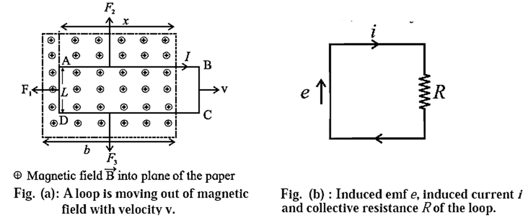
At any instant, let x be the length of the part of the loop in the magnetic field. As the loop moves to the right through a distance dx = vdt in time dt, the area of the loop inside the field changes by And, the Change the magnetic flux dφm through the loop is
dφm = BdA = Blvdt …….(1)
Then, the time rate of change of magnetic flux is
dφm/dt = \(\frac{Blvdt}{dt}\) = Blv …. (2)
By Faraday’5 second law, the magnitude of the induced emf is
|e| = dφm/dt = Blv ……(3)
Due to the motion of the loop, the free electrons (charge, e) in the wire inside the field experience Lorentz force e x . In the wire, this force moves the free electrons in the anticlockwise sense around the loop.
Therefore, the induced conventional current I is in the clockwise sense, as shown.
Figure (b) shows the equivalent circuit of the loop, where the induced emf e is a distributed emf and R is the total resistance of the loop.
∴ I = \(\frac{|e|}{R}=\frac{Blv}{R} \) …………(4)
Now, a straight current-carrying conductor of length L in a magnetic field experiences a force
\(\vec{F}\) = \(I\vec{L}×\vec{B}\)
whose direction can be found using Fleming's left hand rule.
Accordingly, forces \(\vec{F_2}\) and \(\vec{F_3}\) on wires AB and CD, respectively, are equal in magnitude (= IxB), opposite in direction and have the same line of action. Hence, they balance each other. There is no force on the wire BC as it lies outside the field.
The force \(\vec{F_1}\) on the wire AD has magnitude =IlB and is directed towards the left. To move the loop with constant velocity \(\vec{v}\), an external force \(\vec{F}= −\vec{F_1}\)\) must be applied. Therefore, in magnitude,
lF| = F1 = IlB = \(\frac{Blv}{R}.lB\) ……..[from (3)]
= \(\frac{B^2l^2v}{R}\) ……..(4)
Because B, l and R are constants, a force of constant magnitude F is required to move the loop at constant speed v.
Thus, the power or the rate of doing work by the external agent is
p = \(\vec{F}.\vec{v}\) = Fv = \(\frac{B^2l^2v^2}{R}\) ……..(5)
The rate of doing mechanical work is exactly same as the rate of production of heat energy in the circuit/loop.:
Proof : The electric power when an emf e drives a current through a resistance R , i.e., the rate at which thermal energy appears in the loop, is
P = eI = I2R = \((\frac{Blv}{R})^2R\) =\(\frac{B^2l^2v^2}{R}\) …..(6)
From Eqs. (5) and (6), the work done by an external agent in pulling a conducting loop out of a magnetic field appears as thermal energy in the loop.
Eddy Currents:
When a conductor or a portion of a conductor is moved in a magnetic field, "cutting" magnetic field lines, or placed in a changing magnetic field, free electrons in the bulk of the metal begin to circulate in closed paths equivalent to current-carrying loops.
Because these loop currents resemble eddies in a fluid stream, they are also known as eddy or Foucault currents.
- Eddy currents result in generation of heat (energy loss) in the cores of transformers, motors, induction coils, etc.
- To minimize the eddy currents, instead of a solid metal block, cores are made of thin insulated metal strips or laminae.
Applications :
Dead-beat galvanometer: The coil of a pivoted moving coil galvanometer used to measure current is wound on a light aluminium frame. The rotation of the metal frame in a magnetic field causes eddy currents in the frame to oppose the rotation, and the coil quickly comes to rest. As a result, the galvanometer is deadbeat.
Electric brakes : When a conducting plate is pushed into a magnetic field, or pulled out, very quickly, the interaction between the eddy currents in the moving conductor and the field retards the motion. This property of eddy currents is used as a method of braking in vehicles.
Experiment to demonstrate that eddy currents oppose the cause producing them :
Apparatus : A strong electromagnet; two thick copper discs (4” dia, ¼” thick), each attached to a rod about 30” long. One of the discs has several vertical slots, about 80 % of the way up. The pendulums can be suspended from a lab stand by a pivot mount and made to oscillate between closely-spaced pole pieces of the electromagnet.

Experiment : When the electromagnet is turned off, both pendulums swing freely, with some damping caused by air resistance. When the electromagnet is turned on, the slotted pendulum continues to swing, and although slightly more damped, but the solid pendulum immediately stops between the pole pieces of the magnet.
Conclusion : The changing magnetic flux causes eddy currents in the discs as the pendulums enter and exit the magnetic field. The eddy currents' sense is such that they produce a torque that opposes the rotation of the discs about their pivot. This opposing torque acts as a breaking force, dampening the oscillations.
In the case of the solid disc, the continuous volume of the disc offers large unbroken path to the swirling electrons. Thus, the eddy current builds up to a large magnitude. The thicker the disc, the larger is the eddy current and, consequently, the larger the damping.
In the case of the slotted disc, the vertical slots do not allow large eddy current and, consequently, the damping is small.
Self-Inductance:
Concept of self induction : Consider a circuit (coil) in which the current is changing. The changing current will vary the magnitude of magnetic flux linked with the coil (circuit) itself and consequently an emf will be induced in the circuit.

The production of induced emf, in the circuit (coil) itself, on account of a change in the current in it, is termed as the phenomenon of self-inductance.
Explanation :
When the current through a coil goes on changing, the magnetic flux linked with the coil also goes on changing.
The magnetic flux (NΦm ) linked with the coil at any instant is directly proportional to the current (I) through the coil at that instant.
NΦm ∝ I
∴ NΦm = LI
where L is a constant, dependent on the geometry of the coil, called the self-inductance or the coefficient of self-induction of the coil.
The self-induced emf in the coil is
e = \(-\frac{dNΦ_m}{dt}\)=\(-\frac{d}{dt}(LI)\) = \(-L\frac{dI}{dt}\)
In magnitude,
e = \(L\frac{dI}{dt}\)
∴ L = \(\frac{e}{dI/dt}\)
Definition : The self inductance or the coefficient of self induction of a coil is defined as the emf induced in the coil per unit time rate of change of current in the same coil.
OR (using L = N(NΦm/I ), the self inductance of a coil is the ratio of magnetic flux linked with the coil to the current in it.
SI unit : The SI unit of self inductance or coefficient of self induction or inductance as it is commonly called is called the henry (H).
The self-inductance of a coil is 1 henry, if an emf of 1 volt is induced in the coil when the current through the same coil changes at the rate of 1 ampere per second.
The dimensions of self inductance or coefficient of self induction are [ML2T−2I−2].
1 henry = 1 H = 1 V/A.s = 1T.m2/A
| Know This :
Inductor : An inductor is a coil of wire with significant self inductance. If the coil is wound on a nonmagnetic cylinder or former, such as ceramic or plastic, it is called an air-core inductor; . If the coil is wound on a magnetic former, such as laminated iron or ferrite, it is called an iron-core inductor; |
Q. Current passes through a coil shown from left to right. In which direction is the induced emf if the current is (a) increasing with time (b) decreasing in time ?
Ans. From Lenz's law, the induced emf must oppose the change in the magnetic flux.

(a) When the current increases to the right, so is the magnetic flux. To oppose the increasing flux to the right, the induced emf is to the left, i.e., the point A is at a positive potential relative to point B.
(b) When the current to the right is decreasing, the induced emf acts to boost up the flux to the right and points to the right, so that the point A is at a negative potential relative to point B.
Expression for the energy stored in the magnetic field of an inductor :
OR Expression for the electrical work done in establishing a steady current in a coil of self inductance L :
Consider an inductor of self inductance L connected in a circuit. When the circuit is closed, the current in the circuit increases and so does the magnetic flux linked with the coil. At any instant, the magnitude of the induced emf is
e = \(L\frac{di}{dt}\)
The power consumed in the inductor is
P = ei = \(L\frac{dIi}{dt}.i\)
[Alternatively, the work done in moving a charge dq against this emf e is
dw = edq = \(L\frac{dIi}{dt}.dq = Li.di\) (..\((\frac{dq}{dt}=i)\) This work done is stored in the magnetic field of the inductor, dw = du.]
The total energy stored in the magnetic field when the current increases from 0 to I in a time interval from 0 to t can be determined by integrating this expression :
Um = \(\int_{0}^{t} Pdt = \int_{0}^{I} LidI=L\int_{0}^{I} idi = \frac{1}{2}LI^2\)
which is the required expression for the stored magnetic energy.
Now if I = 1, i.e for unit current
Um = ½ L
∴ L = 2Um
Hence, we may define the self inductance of a coil as numerically equal to twice the energy stored in its magnetic field for unit current through the inductor.
Inductances in series or parallel :
We assume that the inductors are so far apart that their mutual inductance is negligible.
If several inductances L1, L2, L3, ... are connected in series or in parallel, then the total inductance is determined by using following relations:
LTotal = L1 + L2 + L3 + ... (Series Combination)
1/LTotal = 1/L1 + 1/L2 + 1/L3 + ...... (Parallel Combination)
Assuming that their mutual inductance can be ignored, the equivalent inductance of a parallel combination of two coils is given by
1/Lparallel = 1/L1 + 1/L2
∴ Lparallel = \(\frac{L_1l_2}{L_1+L_2}\)
Hence, the inductance of two coils connected in parallel is less than the inductance of either coil.
Expression for the self inductance of a solenoid :
Consider a long air-cored solenoid of length l, diameter d and N turns of wire. We assume that the length of the solenoid is much greater than its diameter so that the magnetic field inside the solenoid may considered to be uniform, that is, end effects in the solenoid can be ignored. With a steady current I in the solenoid, the magnetic field within the solenoid is
B = μnI …..(1)
where n = N/l is the number of turns per unit length.
So the magnetic flux through one turn is
Φm= BA = μ0nIA …….(2)
Hence, the self inductance of the solenoid,
L = \(\frac{NΦ_m}{I}\) = (nl)μ0nA = μ0n2lA = μ0n2V …. (3)
= μ0n2l\(\frac{πd^2}{4}\) …. (4)
where V = lA is the interior volume of the solenoid. Equation (3) or (4) gives the required expression.
It is clearly evident that the self inductance of a long solenoid is determined solely by its physical properties, such as the number of wire turns per unit length and volume, instead of the magnetic field or current. This is true for all inductors.
SI unit of magnetic permeability (μo) : Since [n2] = [L2], n2V has the dimension of length. The SI unit of the L being the henry, the SI unit of magnetic permeability (μo) is the henry per metre (H/m).
μo = 4π x 10−7 H/m = 4π x 10−7 T.m/A.
Expression for the self inductance of a narrow air-cored toroid of circular cross section :
Consider a narrow air-cored toroid of circular cross section of radius r, central radius R and number of turns N. So that, assuming r << R, the magnetic field in the toroidal cavity is considered to be uniform, equal to
B = \(\frac{μ_0NI}{2πR}\) = μ0nI …..(1)
where n = \(\frac{N}{2πR}\) is the number of turns of the wire per unit length. The area of cross section, A = πr2
The magnetic flux through one turn is
Φm= BA = μ0nIA …….(2)
Hence, the self inductance of the toroid,
L = \(\frac{NΦ_m}{I}\) = (2πRn)μ0nA = μ02πRn2A = μ0n2V …. (3)
= \(\frac{μ_0N^2r^2}{2R}\) …. (4)
where V = 2πRA is the volume of the toroidal cavity. Equation (3) or (4) gives the required expression.
Energy Density of a Magnetic Field:
Consider a short length l near the middle of a long, tightly wound solenoid, of cross-sectional area A, number of turns per unit length n and carrying a steady current I.

For such a solenoid, the magnetic field is approximately uniform everywhere inside and zero outside. So, the magnetic energy Um stored by this length l of the solenoid lies entirely within the volume Al .
The magnetic field inside the solenoid is
B = μ0nI …..(1)
and if L be the inductance of length l of the solenoid,
L = μ0n2lA …..(2)
The stored magnetic energy,
Um = ½ LI2 …..(3)
and the energy density of the magnetic field (energy per unit volume) is
um = Um/Al = ½ LI2/Al ...(4)
Substituting for L from Eq. (2),
um = \(\frac{1}{2}\frac{μ_0n^2lAI^2}{Al}=\frac{1}{2}μ_0n^2I^2\) ...(5)
∴ um = \(\frac{1}{2}μ_0(\frac{B}{μ_0I})^2I^2=\frac{B^2}{2μ_0}\) ...(6)
Equation (6) gives the magnetic energy density in vacuum at any point in a magnetic field of induction B, irrespective of how the field is produced.
Mutual Inductance (M):
The production of induced emf in a coil due to the change of current in the same coil is called self induction.
Let us consider a case of two coils placed side by side as shown in Fig. a current I1 in coil 1 sets up a magnetic flux Φ21 through one turn of a neighbouring coil 2, magnetically linking the two coils.
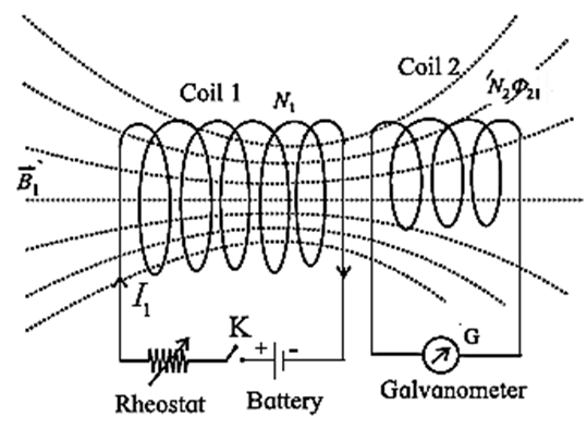
Then, the flux through the N2 tums of coil 2, i.e., the flux linkage of coil 2, is N2Φ21.
N2Φ21 ∝ I1
∴ N2Φ21 = M21I1 ……. (1)
where the constant of proportionality, M21, is called the coefficient of mutual induction of coil 2 with respect to coil 1. If the current I1 in coil 1 changes with time, the varying flux linkage induces an emf e2 in coil 2
e2 = \(−\frac{d}{dt}\)(N2Φ21) = − M21\(\frac{dI_1}{dt}\) …….(2)
Similarly, if we interchange the roles of the two coils and set up a current I2 in coil 2. Then, the flux linkage of N1 turns of coil 1 is N1Φ12 and
N1Φ12 = M12I2 …….(3)
where M12 is the coefficient of mutual induction of coil 1 with respect to coil 2. And, for a varying current I2(t), the induced emf in coil 1 is
e1 = \(−\frac{d}{dt}\)(N1Φ12) = − M12\(\frac{dI_2}{dt}\) …….(4)
It can be shown that M21 = M12 = M (say). So, it is customary to drop the subscripts and write
M = \(\frac{N_2Φ_{21}}{I_1}=\frac{N_1Φ_{12}}{I_2}\) …….(5)
Also, from Eqs. (2) and (4),
M = \(|\frac{e_2}{dI_1/dt}|\) = \(|\frac{e_1}{dI_2/dt}|\) …….(6)
We define mutual inductance using Eq. (5) or Eq. (6)-
The mutual inductance or the coefficient of mutual induction of two magnetically linked coils is equal to the flux linkage of one coil per unit current in the neighbouring coil. OR
The mutual inductance or the coefficient of mutual induction of two magnetically linked coils is numerically equal to the emf induced in one coil (secondary) per unit time rate of change of current in the neighbouring coil (primary).
SI unit and Dimensions : The SI unit of mutual inductance is called the henry (H),
The mutual inductance of a coil (secondary) with respect to a magnetically linked neighbouring coil (primary) is one henry if an emf of 1 volt is induced in the secondary coil when the current in the primary coil changes at the rate of 1 ampere per second.
The dimensions of mutual inductance are lML2T−2I−2] (the same as those of self-inductance).
Q. A long solenoid, of radius R, has n turns per unit length. An insulated coil C of N turns is wound over it as shown. Show that the mutual inductance for the coil-solenoid combination is given by M = μ0πR2nN.

Ans.
We assume the solenoid to be ideal and that all the flux from the solenoid passes through the outer coil C. For a steady current IS through the solenoid, the uniform magnetic field inside the solenoid is
B = μ0nIS …..(1)
Then, the magnetic flux through each turn of the coil due to the current in the solenoid is
ΦCS = BA = (μ0nIS)(πR2) …….(2)
Thus, their mutual inductance is
M = \(\frac{NΦ_{CS}}{I_S}\) = μ0πR2nN …….(3)
Equation (2) is true as long as the magnetic field of the solenoid is entirely contained within the cross section of the coil C. Hence, M does not depend on the shape, size, or possible lack of close packing of the coil.
Coefficient of coupling between two circuits:
Coefficient of magnetic coupling :
The coefficient of magnetic coupling between two inductively coupled coils is defined as the fraction of the magnetic flux produced by the current in one coil (primary) that is linked with the other coil (secondary).
- The coupling coefficient K shows how good the coupling between the two coils is 1 ≥ K ≥ 0.
- In the ideal case when all the flux of the primary passes through the secondary, K = 1. For coils which are not coupled, K = 0.
- Two coils are tightly coupled if K > 0.5 and loosely coupled if K < 0.5.
| Know This : For iron-core coupled circuits, the value of K may be as high as 0.99, for air-core coupled circuits, K varies between 0.4 to 0.8. |
The coefficient of magnetic coupling between two coils depends on :
- the permeability of the core on which the coils are wound
- the distance between the coils
- the angle between the coil axes.
The coefficient of magnetic coupling between two coils is
- maximum when the coils are wound on the same ferrite (iron) core such that the flux linkage is maximum,
- minimum for air-cored coils with the coil axes perpendicular.
Mutual inductance for a pair of inductively coupled coils/ circuits :
Consider a pair of inductively coupled coils having N1 and N2 turns.
A current I1(t) sets up a flux N1Φ1(t) in coil 1 and induces a current I2(t) and flux N2Φ2(t) in coil 2.
Then, the self inductances of the coils are
L1 = N1Φ1/I1 and L2 = N2Φ2/I2 …….(1)
and their mutual inductance is
M = \(\frac{N_2Φ_{21}}{I_1}\) = \(\frac{N_1Φ_{12}}{I_2}\) …. (2)
where N1Φ12 and N2Φ21 are the flux linkages of coils 1 and 2, respectively. If K is the coupling coefficient,
Φ21 = KΦ1 and Φ12 = KΦ2 ….(3)
∴ M = \(\frac{N_2(KΦ_1)}{I_1}\) = \(\frac{N_1(KΦ_2)}{I_2}\)
∴ M = KL1 = KL2 ….(4)
∴ M2 = K2L1L2
∴ M = \(K\sqrt{L_1L_2}\)
This is the required equation.
K is usually less than unity. If K =1, the two coils will be perfectly coupled, and
M = \(\sqrt{L_1L_2}\)
(i) If K > 0.5, the two coils are tightly coupled
(ii) If K<05, the coils are loosely coupled.
(iii) If L1 = L2, then a coil with self-inductance
L is coupled to itself with mutual inductance
M = \(\sqrt{L_1L_2}\) = \(\sqrt{L^2}\) = L
Transformer:
A transformer is an electrical device used for changing the voltage of alternating current from low value to high value or vice versa. Mutual inductance, is the basis of all types of transformers.
Principle : A transformer works on the principle that a changing current through one coil creates a changing magnetic flux through an adjacent coil which in turn induces an emf and a current in the second coil.
Construction : A transformer consists of two coils, primary and secondary, wound on two arms of a rectangular frame called the core (see Fig.).
- Primary coil : It consists of an insulated copper wire wound on one arm of the core. Input voltage is applied at the ends of this coil.
- In a step-up transformer, thick copper wire is used for primary coil. In a step-down transformer, thin copper wire is used for primary coil.
- Secondary coil ; It consists of an insulated copper wire wound on the other arm of the core. The output voltage is obtained at the ends of this coil.
- In a step-up transformer, thin copper wire is used for secondary coil. in a step-down transformer, thick copper wire is used for secondary coil.
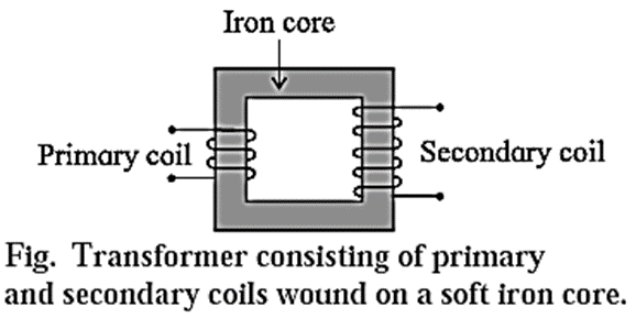
- Core ; It consists of thin rectangular frames of soft iron stacked together, but insulated from each other. A core prepared by stacking thin sheets rather than using a single thick sheet helps reduce eddy currents.
Working : When the primary coil's terminals are connected to a source of alternating emf (input voltage), an alternating current flows through it. In the core of the transformer, the alternating current generates a time-varying magnetic field. As a result, the magnetic flux associated with the secondary coil varies with time according to the current in the primary coil. Therefore, an alternating emf (output voltage) is induced in the secondary coil. .
Types of transformer :
- Step-up transformer ; It increases the amplitude of the alternating emf, i.e., it changes a low voltage alternating emf into a high voltage alternating emf with a lower current.
- Step-down transformer: It decreases the amplitude of the alternating emf, i.e., it changes a high voltage alternating emf into a low voltage alternating emf with a higher current.
Expressions for the emf and current for a transformer in terms of the turns ratio :
An alternating emf VP from an ac source is applied across the primary coil of a transformer, Fig.
This sets up an alternating current I1, in the primary circuit and also produces an alternating magnetic flux through the primary coil such that
vP = −NP \(\frac{dΦ_P}{dt}\) ……..(1)
Where NP is the number of turns of the primary coil and ΦP is the magnetic flux through each turn.
Assuming an ideal transformer (i.e., there is no leakage of magnetic flux), the same magnetic flux links both the primary and the secondary coils, i.e.,
ΦP = ΦS.
As a result, the alternating emf induced in the Secondary coil,
VS = −NS \(\frac{dΦ_S}{dt}\) = −NS \(\frac{dΦ_P}{dt}\) ……..(2)
where NS is the number of turns of the secondary coil.
From Eqs. (1) and (2),
VS/VP = NS/NP …….(3)
Case (1) : If NS > NP, VS > VP . Then, the transformer is called a step-up transformer.
Case (2) : If NS < NP, VS < VP. Then the transformer is called a step—down transformer.
Ignoring power losses, the power delivered to the primary coil equals that taken out of the secondary coil, so that VPIP = VSIS …….(4)
From Eqs. (3) and (4),
\(\frac{I_P}{I_S}=\frac{V_S}{V_P}=\frac{N_S}{N_P}\)
Therefore, the maximum value of the alternating emf induced in the secondary coil of a transformer depends on :
- the ratio of the number of turns of the secondary coil to that of the primary coil
- the maximum value of the alternating emf applied to the primary coil
- the core of the transformer.
Distinguish between a step-up and a step-down transformers :
Step-up transformers
Step-down transformers
The output voltage is more than the input voltage.
The output voltage is less than the input voltage.
The number of turns of the secondary coil is more than that of the primary coil.
The number of turns of the secondary coil is less than that of the primary coil.
The output current is less than the input current.
The output current is more than that of the input current.
The primary coil is made of thicker copper wire than the secondary coil.
The secondary coil is made of thicker copper wire than the primary coil.
We reply to valid query.