Notes Part-1
|
Topics to be Learn : Part-1
|
Nature of light :
- British physicist Maxwell concluded from his electromagnetic theory that light was an electromagnetic wave which travel in free space with a speed c = 2.99792458 x 10⁸ m/s (≈0 x 108 m/s).
- Maxwell concluded that the speed of electromagnetic (em) waves in free space is given by c = \(\frac{1}{\sqrt{ε_0μ_0}}\) where ε0 and μ0 are respectively the permittivity and permeability of free space.
- Light and all other electromagnetic radiations travel at the same speed in free space, which is the maximum possible speed and is considered a universal constant denoted by c.
- Light travels slowly through any medium than it does in free space. The speed of light in a medium depends upon the frequency of light.
- Alternatively, light of a given frequency has different speeds in different mediums.
As per the recent developments nature of light :
- The wave theory of light — light propagating as self-sustaining electromagnetic fields was almost well established by the end of the 19th But then the discovery of photoelectric effect in 1887 and Einstein's interpretation of it in 1905 showed that sometimes light does behave like particles.
- According to Einstein's photon theory, light consists of energy quanta, later called ‘photons’. This compelled the physicists to reconcile with the dual nature of light, wave and particle.
Broad classifications of the field of Optics :
Commonly observed phenomena concerning light can be broadly split into three categories.
(1) Ray optics or geometrical optics:
- Geometrical or ray optics is the idealized domain in which the wavelength of light is negligible in comparison to the size of the optical devices (lenses, mirrors, etc.).
- The simplifying assumptions of geometrical or ray optics are (i) Rectilinear propagation: In a homogeneous and isotropic medium, light travels in a straight line. (ii) When two rays cross each other, they interpenetrate without disturbing each other.
- Geometrical or ray optics can satisfactorily explain reflection, refraction, total internal reflection and dispersion.
(2) Wave optics or physical optics:
- Physical or wave optics deals with situations in which the nonzero wavelength of light must be taken into account.
- It deals with behaviours that are specifically attributable to the wave nature of light, e.g., interference, diffraction, polarization and Doppler effect.
(3) Particle nature of light :
- Quantum optics deals with phenomena arising from interaction of light with matter; emmision of spectral lines, photoelectric effect, Compton effect, etc. are attributed to the quantum or particle nature of light and are treated by Quantum Mechanics.
- With the modern quantum theory, mathematical techniques like Fourier analysis and insights of communications theory, the field of applied Optics has flourished from the second half of the twentieth century.
- Lasers and LEDs have led to the discovery of new optical effects and new devices, optical communication system, holography, etc.
Ray optics or geometrical optics:
The main focus of geometrical optics is the study of image generation using prisms, mirrors, and lenses. It is based on four fundamental laws/ principles.
(i) In a homogeneous, isotropic medium, light moves in a straight line. When a material is homogeneous, its properties are the same throughout, and when it is isotropic, they are the same in every direction.
(ii) Two or more rays can intersect at a point without affecting their paths beyond that point.
(iii) Laws of reflection:
- Reflected ray lies in the plane formed by incident ray and the normal drawn at the point of incidence; and the two rays are on either side of the normal.
- Angles of incidence and reflection are equal.
(iv) Laws of refraction: These apply at the boundary between two media
- The refracted ray lies in the plane of incidence, which is the plane of the incident ray and the normal to the interface of the two mediums at the point of incidence.
- For a monochromatic ray of light passing obliquely from one medium to another, the
- ratio of the sine of the angle of incidence to the sine of the angle of refraction is constant for that pair of mediums and is equal to the refractive index of the second medium relative to the first for that frequency. This is called Snell’s law.
If i is the angle of incidence in medium 1 of refractive index n1, and r is the angle of refraction in medium 2 of refractive index n2.
\(\frac{sin\,i}{sin\,r}\) = 1n2 = \(\frac{n_2}{n_1}\) or n1 sin i = n2 sin r
| Know This :
Interestingly, all the four laws stated above can be derived from a single principle called Fermat’s principle. It says that “While travelling from one point to another by one or more reflections or refractions, a ray of light always chooses the path of least time”. Ideally it is the path of extreme time, i.e., path of minimum or maximum time. |
When a narrow parallel beam of light meets an interface, i.e., a surface separating two mediums :
- In general, when a narrow parallel beam of light meets an interface, i.e., a surface separating two mediums, it is partly reflected and the remainder passes into the new medium.
- Because of this reflection, occurring simultaneously with refraction, we can see the image of the surrounding objects faintly reflected from the surface of a pool of water or a flat glass sheet. The fraction of the incident light that is reflected increases with the angle of incidence.
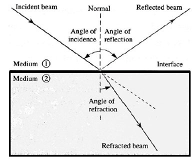
- For oblique incidence, the beam of light bends as it enters the new medium. This change of direction as light passes obliquely from one medium to another results from a change in the speed of light and is called refraction.
Cartesian sign convention in ray optics :
- In a ray diagram, the principal axis is drawn horizontal and the incident rays are always shown directed from the left to the right.

- The pole of a spherical surface, or the optical centre of a lens, and the principal axis are respectively taken to be the origin and the x-axis of the Cartesian coordinate axes.
- Horizontal distances are measured from the origin; distances to the right are considered positive while those to the left negative.
- Vertical distances are measured from the principal axis; distances above are considered positive while those below negative.
Reflection:
Reflection from a plane surface:
Characteristics of an image formed by a plane surface/mirror : For an object in front of a plane surface/mirror, the image is virtual, erect, laterally inverted and of the same size. The image is behind the mirror, the image distance being equal to the object distance.
Formula for the number of images formed by two plane mirrors inclined at an angle θ :
For two plane mirrors inclined at an angle θ, calculate n = (3600)/θ Then, by the number of images (N) seen is given by the following cases :
Case i: If n is even integer, N = n − 1, irrespective of the object position.
Case ii : If is an odd integer,
(i) N = n, if the object is off the angle bisector,
(i) N = n − 1, if the object is on the angle bisector.
Case III : If n is not an integer, N = |n| = floor (n).
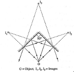
Table :
| Angle θ0 | n = (3600)/θ | Position of the object | N |
| 120 | 3 | On angle bisector | 2 |
| 120 | 3 | Off angle bisector | 3 |
| 110 | 3.28 | Anywhere | 3 |
| 90 | 4 | Anywhere | 3 |
| 80 | 4.5 | Anywhere | 4 |
| 72 | 5 | On angle bisector | 4 |
| 72 | 5 | Off angle bisector | 5 |
| 60 | 6 | Anywhere | 5 |
| 50 | 7.2 | Anywhere | 7 |
Reflection from curved mirrors:
Terms for a spherical mirror or surface :
- Pole : The centre of a spherical mirror or surface is called the pole of the spherical mirror or surface.
- Centre of curvature : The centre of the sphere, of which the spherical mirror or surface is a section, is called the centre of curvature of the spherical mirror or surface.
- Radius of curvature : The radius of the sphere, of which the spherical mirror or surface is a section, is called the radius of curvature of the spherical mirror or surface.
- Principal axis : The line passing through the pole and the centre of curvature of a spherical mirror or surface is called the principal axis of the spherical mirror or surface.
Principal focal point of a spherical mirror : A narrow parallel beam of light,
parallel to the principal axis, after reflection from a spherical mirror either converges to (for a concave mirror) or appears to diverge from (for a convex mirror) a single point on the principal axis. This point is called the principal focal point or principal focus of the spherical mirror.
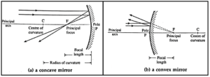
Relation between the focal length,f, and the radius of curvature, R, of a spherical mirror :
(i) For a spherical mirror, the principal focus is midway between the pole and centre of curvature. ∴ f = R/2
(ii) The relation between the object distance, u, the image distance, v, and the focal length, f, of a spherical mirror is called the mirror equation.
The mirror equation : \(\frac{1}{f}=\frac{1}{v}+\frac{1}{u}\)
Focal plane : A narrow parallel beam of light, close to but not parallel to the principal axis, converges at or appears to diverge from a single point on a plane perpendicular to the principal axis and passing through the principal focus. Such a plane is called the focal plane.

- Note : All points on a focal plane are focal points, so that there are an infinite number of focal points. The point of intersection of the principal axis with the focal plane is the principal focal point or principal focus.
Lateral magnification : The lateral magnification produced by a spherical mirror is defined as the ratio of the image height (hi) to the object height (ho).
Lateral magnification, m = hi/ho = − v/u
where u = object distance, v = image distance.
The minus sign takes into account the Cartesian sign convention.
If the calculated value of m is positive, the image is erect; the image is inverted if m is negative.
Image formation by a concave mirror :
- Object at infinity : A real image is formed in the focal plane. It is inverted and highly diminished relative to the object.
- Object between infinity and centre of curvature : A real image is formed between the focal plane and centre of curvature. It is inverted and diminished relative to the object.
- Object at the centre of curvature : A real image is formed at the centre of curvature. It is inverted relative to the object and of the same size as
- that of the object.
- Object between the centre of curvature and focal plane : A real image is formed beyond the centre of curvature. It is inverted and magnified relative to the object.
- Object in the focal plane : An imperceptible real image is formed at infinity. It is inverted and highly magnified relative to the object.
- Object between the pole and focal plane : A virtual image is formed behind the mirror. It is erect and magnified relative to the object.
Image formation by a convex mirror :
- If the object is at infinity, the image is formed at the principal focus of the mirror, behind the mirror. It is virtual, erect and highly diminished.
- If the object is at any finite distance from the mirror, the image is formed behind the mirror, between the pole and principal focus of the mirror. It is virtual, erect and diminished.

Focal power of a spherical mirror :
- The focal power of a spherical mirror gives the degree to which a mirror can converge or diverge a parallel beam of light and is defined as the negative reciprocal of its focal length : P= −1/f
- The SI unit of the focal power is the diopter (symbol D). One dioptre is the power of a mirror of focal length one metre.
- The reciprocal, 1/f, actually represents curvature of a spherical surface of which f is the radii.
- Figure shows plane waves reflected by a concave mirror toward its focal point F.
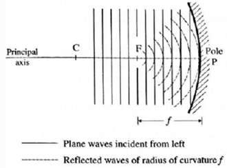
- The lines represent the crests of light waves that are everywhere perpendicular to the corresponding light rays that could have been drawn from object at infinity to the image point at F.
- The shorter the focal length f the greater is the curvature of the reflected waves, i.e., the more is the converging power of the mirror.
- That is, P ∝ 1/f .
- The power of a converging mirror is taken to be positive. The minus sign is included
- because, by sign convention, f of a concave (converging) mirror is negative.
Spherical aberration:
A spherical mirror forms reasonably sharp image if its aperture is small compared with its focal length. But if the mirror size is large, the peripheral or abaxial rays reflected from the outer edges are brought to a focus closer to the pole than the paraxial rays. This focusing defect is called spherical aberration.
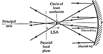
The distance between the paraxial and abaxial foci is called the longitudinal spherical aberration (LSA).
Methods to reduce Spherical aberration:
Spherical aberration can be reduced by allowing only paraxial rays. This can be achieved by
- using a mirror of small size
- using a circular iris diaphragm, called an aperture.
With any of these two restrictions, sharp images of objects at any distance greater than the focal length may be formed on a screen, since bundles of parallel rays close to the axis and making only small angles with it are brought to a sharp focus in the focal plane.
If, however, the light is not confined to the paraxial region, parallel incident rays at increasing distances from the principal axis cross the axis closer to the mirror, as shown in above Fig.If a small screen is placed at the paraxial focal plane F and then moved toward the mirror, a point is reached where the size of the circular image spot is a minimum. This circular spot is indicated in Fig. and is called the circle of least confusion.
Parabolic mirror:
A parabola is a locus of points equidistant from both a point and a line, respectively called the focus and directrix of the parabola.
The lines l1, l2, l3.. in the following figure represent the distance of the focus and different points on the directrix from points on the parabola.

Every point on the parabola is equidistant from the directrix and the focus.
A paraboloidal mirror in Fig. is a surface of revolution formed by revolving a parabola about the principal axis. The figure shows the mirror in cross section.
- Spherical aberration can be eliminated by using a paraboloidal mirror. Such a mirror brings all rays parallel to the axis of the paraboloid to a single focus. Contrarily, a small source of light located at the focal point of a parabolic reflector becomes a parallel beam after reflection.
- Use : This principle is used in spotlights, searchlights and automobile headlights.
Refraction:
Absolute refractive index of a medium : Absolute refractive index, or the refractive index of a medium relative to free space, is defined as the ratio of the speed of light in free space to that in the medium.
n = \(\frac{\text{speed of light in free space}}{\text{speed of light in medium}}=\frac{c}{v}\)
Relative refractive index : When a monochromatic light passes from medium 1 (in which its speed is v1) into medium 2 (in which its speed is v2), the refractive index of medium 2 relative to medium 1 is defined as the ratio of the speed of light in medium 1 to that in medium 2.
1n2 = \(\frac{\text{speed of light in in medium 1}}{\text{speed of light in medium 2}}=\frac{v_1}{v_2}\) …..(1)
Above equation can be written as
1n2 = \(\frac{1/v_2}{1/v_1}\)
so that multiplying and dividing the right hand side by c, the speed of light in free space,
1n2 = \(\frac{c/v_2}{c/v_1}=\frac{n_2}{n_1}\)
where n1 = c/v1 and n2 = c/v2 are respectively the absolute refractive indices of the mediums 1 and 2. Therefore, the refractive index of medium 1 relative to medium 2 is
2n1 = \(\frac{v_2}{v_1}=\frac{n_1}{n_2}=\frac{1}{n_2/n_1}\) = 1/1n2
Notes : (i) Monochromatic light means light of single frequency. (ii) The refractive index of medium 2 relative to medium 1 is also denoted by 1μ2.
Know This :
|
Illustrations of refraction:
(i) The speed of light in free space (or air), c = 3 x 10⁸ m/s. The speeds of yellow light in water and glass are 2.25 x 10⁸ m/s and 2 x 10⁸ m/s, respectively.
∴ The absolute refractive index, for yellow light, for water,
nw = \(\frac{c}{v_w}=\frac{3×10^8}{2.25×10^8}=\frac{3}{9/4}=\frac{3}{4}\)
and for glass ng = \(\frac{c}{v_g}=\frac{3×10^8}{2×10^8}=\frac{3}{2}\)
The refractive index of glass w.r.t. water is
wng = \(\frac{v_w}{v_g}=\frac{2.25×10^8}{2×10^8}=\frac{9/4}{2}=\frac{9}{8}\)
Also wng = \(\frac{n_g}{n_w}=\frac{3/2}{4/3}=\frac{9}{8}\)
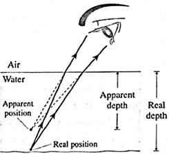
(ii) The bottom of a water body when seen from air : The rays of light coming from the bottom of a water body bend away from the normal as they travel from a denser medium (water) to a rarer medium (air). Hence, they appear to come from a point above the bottom to an observer looking from air as shown in Fig. Therefore, the bottom of the water body appears raised.
(iii) A stick or pencil kept obliquely in a glass containing water appears broken as its part in water appears to be raised.
Prove : When the bottom of a water body is viewed from air at nearly normal incidence, apparent depth = \(\frac{real\,depth}{\text{refractive index of water}}\)
Proof :
The essential features of the situation are shown in below Fig.
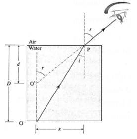
A light ray that leaves the bottom edge of the water body at O is refracted at point P and appears to the observer to be coming from a virtual image of the object at O’, whose depth d is less than the depth D of point O; D is called the real depth and d is called the apparent depth.
Let n1 and n2 be the absolute refractive indices of the water and air, respectively.
At nearly normal incidence, i and r are very small, so that by small angle approximation,
sin i ≈ tan i = x/D
and sin r ≈ tan r = x/d
By Snell‘s law, n1 sin i = n1 sin r
∴ 2n1 = \(\frac{n_1}{n_2}=\frac{sin\,i}{sin\,r}=\frac{x/d}{x/D}=\frac{D}{d}\)
∴ Apparent depth, d = \(\frac{Real\,depth\,(D)}{._2n_1}\)
where 2n1 = refractive index of water w.r.t. air.
Total internal reflection:
Whenever a light ray comes across a medium of different refractive index, there is simultaneous reflection and refraction.
From Snell's law, \(\frac{sin\,i}{sin\,r}=\frac{n_2}{n_1}\)
sin r = \(\frac{n_1}{n_2}\)sin i ……. (1)
When a light is incident from a rarer medium, n1 = n2, the angle of refraction r is less than the angle of incidence i. In this circumstance, some part of the incident light always passes into the second medium for any incident angle i = 90°.

When a light ray travelling in a denser medium is incident normally (i = 0°) onto an interface, the ray passes undeviated into the rarer medium as shown by the ray 1 in Fig. However, for an oblique incidence from a denser medium, n2 = n1 in Eq. (1) means sin r is greater than sin i, so that r > i (the ray 2 in the figure). As i increases from a small value, sin i approaches 1n2 \((=\frac{n_2}{n_1})\), sin r approaches unity and r approaches 90°. Under these conditions, the refracted ray (the ray 3 in the figure) grazes the interface, just escaping the denser medium.
Hence, the angle i for which sin r = 1, i.e., r = 90°, is called the critical angle of incidence (iC) for the pair of mediums.
Critical angle : When a light ray travelling in a denser medium (of refractive index n1) meets an interface with a rarer medium (of refractive index n2), the angle of incidence in the denser medium for which the beam just emerges into the rarer medium, i.e., the angle of refraction in the rarer medium is 90°, is called the critical angle for the two mediums.

If i and r are the angles of incidence and refraction, then
n1 sin i = n2 sin r [Snell's law]
At the critical angle, i = iC and r = 90°, so that
n1 sin iC = n2 ['.' sin r = sin 90° = 1]
∴ sin iC = \(\frac{n_2}{n_1}\) = 1n2 = 1/2n1
Here 2n1 is the refractive index of the denser medium relative to the rarer medium.
Thus, sin iC = 1/2n1
- For i > iC, sin i is greater than 1n2, and Eq. (1) then gives a value for sin r greater than unity.
- Since, there cannot be any real angle that satisfies the equation, there is no refracted ray.
- For an angle of incidence in the denser medium greater than the critical angle, the incident ray is completely reflected at the interface (the ray 4 in the figure) and no light enters the rarer medium. This phenomenon is called total internal reflection.
Conditions for total internal reflection :
- A ray of light must approach an interface from the denser medium.
- The angle of incidence in the denser medium must be greater than the critical angle of incidence for the pair of mediums.
Applications of total internal reflection:
- Optical fibre : Though little costly for initial set up, optic fibre communication is undoubtedly the most effective way of telecommunication by way of EM waves. Optical fibres used in communications and endoscopy (the visual observation of various internal body cavities) transmit light signals by total internal reflection.
- Totally reflecting prisms are used in reflex (SLR) cameras, binoculars and periscopes.
- A diamond gem is given strategic cuts so that total internal reflections give the gem its sparkling brilliance.
Construction and working of an optical fibre :
Construction : An optical fibre is a sort of flexible ‘light pipe’ within which light is constrained to travel as a result of successive total internal reflections. An optical fibre consists of a transparent core filament surrounded by a plastic matrix called cladding (Fig.).
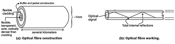
The core has a diameter of few thousandths of a millimetre and is usually made of glass. The cladding has a refractive index lower than that of glass. Each composite
filament, called an optical fibre, is very flexible and an optical transmission line is made up of a bundle of such optical fibres enclosed in a protective plastic jacket.
Working : Because the refractive index of the core is more than that of the cladding, light travels along the core by total internal reflections if it strikes the interface between the core and the cladding at an angle of incidence more than the critical angle.
Advantages of optic fibre communication :
- Broad bandwidth (frequency range): For TV signals, a single optical fibre can carry over 90000 channels (independent signals).
- Immune to EM interference: Being electrically non-conductive, it is not able to pick up nearby EM signals.
- Low attenuation loss: The loss is lower than 0.2 dB/km so that a single long cable can be used for several kilometers.
- Electrical insulator: No issue with ground loops of metal wires or lightning.
- Theft prevention: It is does not use copper or other expensive material.
- Security of information: Internal damage is most unlikely. Any attempt to tap the optically transmitted signal can be easily detected. This feature makes it ideal for military, banking and computer network applications.
Working of totally reflecting prism :
The critical angle for crown glass—air interface is about 41.2°. If a ray of light is incident on the interface through glass at an angle greater than this, the ray is totally internally reflected.
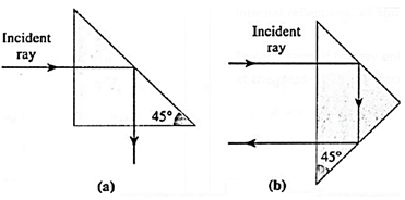
The simplest type of a totally reflecting prism is a right prism (45° — 45° — 90° ). Aray of light may be internally reflected only once at the hypotenuse, as shown
in below Fig. (a), or may enter and leave through the hypotenuse after undergoing two internal reflections, as shown in Fig. (b).
In each case, if the ray enters one face of the prism normally, the angle of incidence at the glass-to-air interface is 45°, i.e., greater than the critical angle.
Light beam deviated through (a) 90° (b) 180° :

Prism binoculars:
A prism binocular is a pair of monocular terrestrial telescopes mounted side by side, one for each of the two eyes.
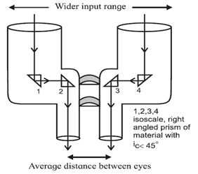
Binoculars using only two cylinders have a limitation of field of view as the distance between the two cylinders can’t be greater than that between the two eyes. This limitation can be overcome by using two right angled glass prisms ( iC ~ 420 ) used for total internal reflection as shown in the below Fig. Total internal reflections occur inside isosceles, right angled prisms.
- Rays of light entering through the objectives undergo two total reflections in each prism.
- Each prism turns a ray by 180°, the second prism of a pair effectively turning it towards the eyepiece.
- The two prisms are mounted, with their cross sections perpendicular to each other such that the 180° turn by each produces left-right and top-down lateral inversions, therefore giving an erect final image.
Advantages of a prism binocular over a traditional binocular :
Use of totally reflecting prism :
- Minimizes light loss and accomplishes the function of erecting an image in less space.
- Increases the separation of the objectives, thereby increasing the stereoscopic effect for a better depth perception.
- Doubles-back the light rays which enables long-focus objective lenses to be used in short tubes, thus giving higher magnifying power
Advantages of a totally reflecting prism over a front-silvered mirror :
- Reflection from a front-silvered mirror is always partial. A part of the incident intensity passes into the silver coating and is absorbed. Hence, the intensity of the reflected ray is less than that of the incident ray.
- In comparison, in a totally reflecting prism the reflected intensity equals the incident intensity. A totally reflecting prism, unlike the silver coating of a front-silvered mirror, does not degrade with moisture and dirt.
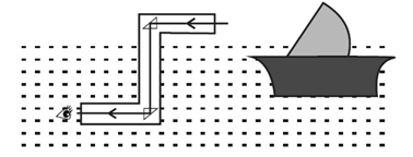
Periscope :
- A periscope is an optical equipment used to observe above or around a barrier that prevents direct line-of-sight observation from the position of the observer.
- It is often employed in naval submarines to see hostile ships and targets from beneath the surface of the sea.
- It directs light beams via a tube using two completely reflecting prisms. The light from an object is rotated 90 degrees down the periscope tube. Another prism at the bottom of the periscope tube bends the light 90° into the viewer's eye.
Refraction at a spherical surface and lenses:
Lenses:
- Concavo-convex and convexo-concave lenses are commonly used for spectacles of positive and negative numbers, respectively.
- Convex lenses have positive focal length and converge the incident beam while concave lenses have negative focal length and diverge the incident beam.
Terms of Lenses :
Optical centre of a lens : The optical centre of a thin lens is a point on the principal axis coinciding with the centre of the lens such that a light ray directed towards it passes through the lens undeviated.
Principal focus of a lens : The principal focus of a lens is a point on the principal axis whore light rays (i) parallel to the principal axis are convergent or appear to diverge from, (ii) diverging from, or appearing to converge, are rendered parallel to the principal axis after refraction through the lens.
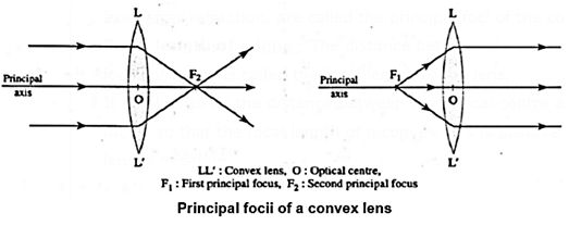
Principal foci of a convex (converging) lens: The two points on the principal axis where light rays parallel to the principal axis are brought together, and from where diverging light rays are rendered parallel to the principal axis, after refraction, are called the principal foci of the convex (converging) lens.
Principal foci of a concave (diverging) lens : The two points on the principal axis such that light rays parallel to the principal axis appear to diverge from them, and to which light rays appearing to converge are rendered parallel to the principal axis, after refraction, are called the principal foci of the concave (diverging) lens.

Focal length of a lens : The distance between the optical centre and the principal focus of a lens is called the focal length of the lens.
It is taken to be the distance between the optical centre and the second principal focus, so that the focal length of a convex lens is positive while that of a concave lens is negative.
Refraction at a single spherical surface:
Consider a convex spherical surface APB separating two transparent mediums 1 and 2. Their absolute refractive indiccs are n1 and n2, respectively, with n2 > n1. Let O be a luminous point object on the principal axis in the rarer medium, as shown in Fig.

- The ray OP along the principal axis is incident normally on the spherical surface and passes into the denser medium undeviated.
- A second ray OD is incident obliquely on the surface at an angle of incidence i with the normal CN.
- Let the angle of refraction r for this ray be such that the refracted ray meets the ray OP forming a real point image I on the principal axis.
- The angles made by the incident ray OD, the refracted ray DI and the normal CN with the principal axis are α, β and ν, respectively.
Assumption : To make small angle approximations (sin θ ≈ θ and tan θ ≈ θ), θ in radian), we consider the ray OD to be a pamxial ray (i.e., close to and almost parallel to the axis). Then, i, r, α, β and ν may be treated as very small angles.
Derivation : By Snell's law,
n1 sin i = n2 sin r or n1 i = n2 r
In triangles DOC and DIC, i and ν are the respective exterior angles.
∴ i = α + ν
And ν = β + r or r = ν − β
∴ n1(α + ν)= n2(ν − β)
∴ n1α + n2β = (n2 − n1)ν
Now α = \(\frac{arc\,PD}{PO}\), β = \(\frac{arc\,PD}{PI}\), ν = \(\frac{arc\,PD}{PC}\)
∴ n1\(\frac{arc\,PD}{PO}\) + n2\(\frac{arc\,PD}{PI}\) = (n2 — n1)\(\frac{arc\,PD}{PC}\)
∴ \(\frac{n_1}{PO}+\frac{n_2}{PI}=\frac{n_2-n_1}{PC}\)
According to the Cartesian Sign convention,
object distance PO= −u, image distance PI = +v and radius of curvature PC = +R
∴ \(\frac{n_1}{-u}+\frac{n_2}{v}=\frac{n_2-n_1}{R}\)
∴ \(\frac{n_2}{v}-\frac{n_1}{u}=\frac{n_2-n_1}{R}\)
- Note : Although this relation has been derived by considering a particular case, the application of the sign conventions makes this a general relation for refraction at a spherical surface. It is true for both convex and concave surfaces, n1 > n2 or n2 > n1, real or virtual images, and real or virtual object’s.
Lens makers’ equation:
Consider a thin convex lens (refractive index n2) placed in a rarer medium (refractive index n1,). Let R1 and R2 be the radii of curvature of the two spherical surfaces of the lens.
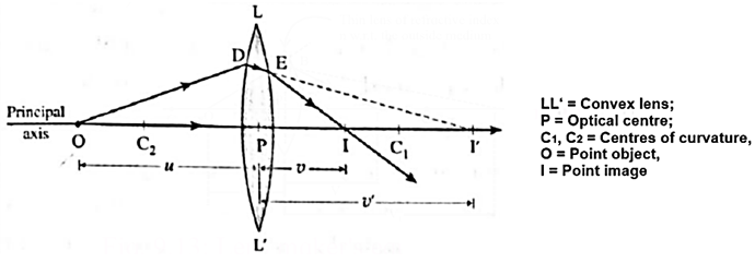
Consider a luminous point object O on the principal axis in front of the lens at a distance u from the optical centre P (Fig.).
The ray OP incident on the lens along its principal axis passes through uncleviated.
A paraxial ray OD suffers two refractions, at the two spherical surfaces of the lens.
For refraction at a spherical surface,
\(\frac{n_2}{v}-\frac{n_1}{u}=\frac{n_2-n_1}{R}\) ……(1)
Now, for the refraction at the first surface, the refracted ray is DE.
If there was no second surface, the ray DE would have proceeded in the denser medium and met the ray OP, thus forming a real image at I’.
Let PI’ = v’.
Thus, in this case, the object distance is u, the image distance is v’ and the radius of curvature is R1.
Substituting these values in Eq. (1),
\(\frac{n_2}{v'}-\frac{n_1}{u}=\frac{n_2-n_1}{R_1}\) ……(2)
But the denser medium does not extend far beyond the first surface so that the ray DE suffers another refraction at the second surface and emerges out into the rarer medium.
This emergent ray meets the ray OP at I which is the image produced by the lens. Let PI = v.
Thus, for the refraction at the second surface, the incident ray DE is in a medium of refractive index n2, the refracted ray is in a medium of refractive index n1, and I’ acts as the virtual object with object distance PI’ = v’.
Accordingly, Eq. (1) for this case becomes
\(\frac{n_1}{v}-\frac{n_2}{v'}=\frac{n_1-n_2}{R_2}=-\frac{n_2-n_1}{R_2}\)……(3)
Adding Eqs. (2) and (3) eliminates v’ and we get,
\(\frac{n_1}{v}-\frac{n_1}{u}\) = \((\frac{n_2}{n_1})(\frac{1}{R_1}-\frac{1}{R_2})\)
or, dividing by n1,
\(\frac{1}{v}-\frac{1}{u}\) = (n2-n1)\((\frac{1}{R_1}-\frac{1}{R_2})\) ……(4)
The focal length of a lens is the image distance when the object is at infinity, i.e., v = f for u = ∞. Substituting these values in Eq. (4),
\(\frac{1}{f}\) = (1n2 − 1)\((\frac{1}{R_1}-\frac{1}{R_2})\) ……(5)
Where 1n2 = \(\frac{n_2}{n_1}\)
Equation (5) is called the lens makers’ equation.
Since the right hand sides of Eqs. (4) and (5) are the same, equating their left hand sides gives
\(\frac{1}{f}=\frac{1}{v}-\frac{1}{u}\)
This is the thin lens equation
Special cases:
Most popular and most common special case is the one in which we have a thin, symmetric, double lens. In this case, R1 and R2 are numerically equal.
Case 1 :
The focal length and radii of curvature are numerically equal for a thin, symmetric lens — either double convex or double concave — made of the common crown glass, whose refractive index, n ≈ 1.5.
For an equiconvex lens, by the sign convention, R1= R and R2 = −R (R>0). Then, by lens makers’ formula,
\(\frac{1}{f}\) = (n − 1)\((\frac{1}{R_1}-\frac{1}{R_2})\)
= (n − 1)\((\frac{1}{R}-\frac{1}{-R})\)
= \(\frac{2(n-1)}{R}\)
∴ For n = 1.5, \(\frac{1}{f}\) = (n − 1)\(\frac{2(1.5-1)}{R}=\frac{1}{R}\)
∴ f = R
For an equiconcave lens, R1 = − R and R2 = R
∴ \(\frac{1}{f}\) = (n — 1)\((\frac{1}{-R}-\frac{1}{R})\) = \(-\frac{2(n-1)}{R}\)
∴ For n = 1.5 , \(\frac{1}{f}=-\frac{1}{R}\)
∴ f = −R
Case 2 :
The focal length is numerically equal to twice the radius of curvature for a thin planoconvex or planoconcave lens made of crown glass (n = 1.5).
(i) For a planoconvex lens, R1 = ∞ and R2 = −R (or R1 = R and R2 = ∞ ). For both cases,
\(\frac{1}{f}\) = \(\frac{(n-1)}{R}\)
= \(\frac{1.5-1}{R}=\frac{1}{2R}\) ...(for n = 1.5)
∴ f = 2R ..(positive)
(ii) For a planoconcave lens, R1 = ∞ and R2 = R (or R1 = −R and R2 = ∞ ). For both cases,
\(\frac{1}{f}\) = \(-\frac{n-1}{R}\)
= \(-\frac{1.5-1}{R}=-\frac{1}{2R}\) ...(for n = 1.5)
∴ f = −2R ..(negative)
Expression for the resultant focal length of a combination of two or more thin lenses in contact :
When two or more thin lenses—of focal lengths, f1, f2, f3,…. are in contact, their resultant focal length f is given by
\(\frac{1}{f}=\frac{1}{f_1}+\frac{1}{f_2}+\frac{1}{f_3}...\)
Depending on whether an individual lens is converging or diverging, its focal length must be substituted with the appropriate sign. The combination will act as a converging lens only if f is positive.
Expression for the resultant focal length of a combination of two thin lenses in air separated by a distance d :
Consider two thin lenses, of focal lengths f1 and f2, placed coaxially in air and separated by a distance d. The resultant focal length f is given by
\(\frac{1}{f}=\frac{1}{f_1}+\frac{1}{f_2}-\frac{d}{f_1f_2}...\)
where f1 and f2 are substituted with the appropriate sign.
Power Lens : The power of a lens, which gives the measure of the degree to which a lens can converge or diverge a parallel beam of light, is defined as the reciprocal of its focal length : P = \(\frac{1}{f}\).
- The SI unit of the power of a lens is the diopter (symbol D). One dioptre is the power of a lens whose focal length is one metre.
Combined power of two or more thin lenses placed in contact :
When two or more thin lenses are placed in contact, their resultant or combined focal length (f) is given by \(\frac{1}{f}=\frac{1}{f_1}+\frac{1}{f_2}+\frac{1}{f_3}...\)
Where f1, f2, f3,…. are the focal lengths of the lenses in contact. Hence, the resultant or combined power P of a combination of two or more thin lenses in contact is equal to the sum of their individual powers : P = P1 + P2 + P3 + ...,
Where P1 = \(\frac{1}{f_1}\), P2 = \(\frac{1}{f_2}\), P3 = \(\frac{1}{f_3}\), ..., are the powers of the lenses in contact.
Combined power of two thin lenses in air separated by a distance d :
For two thin lenses, of focal powers P1 and P2, placed coaxially in air and separated by a distance d, their combined power is
P = P1 + P2 − d(P1P2)
Linear magnification : The linear magnification produced by a lens is the factor by which the image size is changed from the object size. The linear magnification,
m = \(\frac{h_i}{h_o}=\frac{v}{u}\)
where ho = object height, hi = image height, u = object distance, and v = image distance.
Significance of magnitude and sign of linear magnification :
- If the magnitude of linear magnification is less than one, it means the image is smaller than the object. On the contrary, if it is greater than one, it means the image is larger than the object.
- The sign of the linear magnification indicates whether the image is erect or inverted relative to the object. For an erect image, the magnification is positive; while for an inverted image, the magnification is negative.
We reply to valid query.