Notes-Part-1
|
Topics to be Learn : Part-1
|
Introduction :
Faraday conducted a series of experiments in England in 1831 concerning the generation of electric current via magnetic flux.
The results of these experiments resulted in Faraday's law of induction, a fundamental and important law of electromagnetism.
Faraday's experimental observations are as below:
Faraday’s magnet and coil experiment :
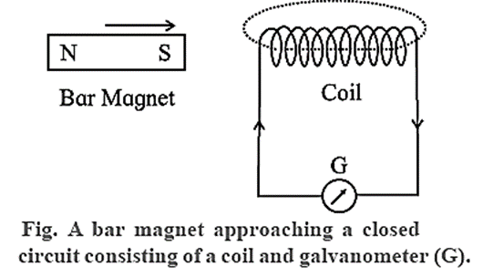
The terminals of a copper coil of several turns are connected to a sensitive galvanometer.
- i) When a magnet approaches a closed circuit consisting of a coil, it produces a current in it. This current is known as induced current. As long as the magnet is in motion, the galvanometer shows a deflection
- ii) When the magnet is taken away from the closed circuit a current is again produced but in the opposite direction with respect to that in experiment (i).
- iii) If instead of the magnet, the coil is moved towards the magnet or away from it, an induced current is produced in the coil (i.e., in the closed circuit).
- iv) If the polarity of approaching or receding magnet is changed the direction of induced current in the coil is also changed.
- v) The magnitude of induced current depends on the relative speed of the coil with respect to magnet. It also depends upon the number of turns in the coil.
- vi) The induced current exists so long as there is a relative motion between the coil and magnet.
Conclusion : A current is induced in an electric circuit whenever the magnetic flux linked with the circuit keeps on changing as a result of relative motion of a magnet and the circuit.
Faraday’s coil-coil experiment :
Instead of a magnet and a closed circuit, two coils with their planes facing each other (Fig.) also produce similar effects as mentioned above in experiments from (i) to (vi).
One coil is connected in series with a battery, rheostat and key while the ends of the other coil are connected to a galvanometer (G). The coil 1 which consists of a source of emf (a battery) is termed as primary coil while the coil 2 as secondary coil. With these two coils, following observations are made:
- (i) When the circuit in the primary coil is closed or broken, a momentary deflection is produced in the galvanometer at the time of make or break. When the circuit is closed or broken the directions of deflection in the galvanometer are opposite to each other.
- (ii) When there is a relative motion between the two coils (with their circuits closed), an induced current is produced in the secondary coil but it exists so long as there is a relative motion between the coils.
- (iii) Whenever the current in the primary coil is changed (either increased or decreased) by sliding the rheostat-jockey, a deflection is produced in the galvanometer. This indicates the presence of induced current. The induced current exists so long as there is a change of current in the primary coil.
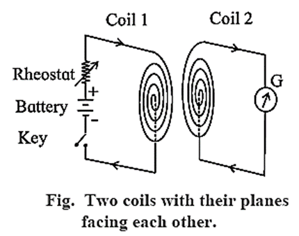
Conclusion : A current is induced in an electric circuit whenever the magnetic flux linked with the circuit keeps on changing, either as a result of changing current in a nearby circuit or due to relative motion between them.
- The results of the above two experiments show that an induced emf is produced whenever there is a change in magnetic flux (caused by a magnet or a current carrying coil) inside a coil. If the flux is decreased instead of increased, the direction of induced emf reverses, and vice versa.
Faraday's Laws of Electromagnetic Induction:
The phenomenon of production of emf in a conductor or circuit by a changing magnetic flux through the circuit is called electromagnetic induction.
Faraday’s laws of electromagnetic induction :
- First law : Whenever there is a change in the magnetic flux associated with a circuit, an emf is induced in the circuit.
- Second law : The magnitude of the induced emf is directly proportional to the time rate of change of magnetic flux through the circuit.
Flux rule :
If φ is the magnetic flux linked with the coil at any instant t, then the induced emf.
e ∝ dφ/dt …..(1)
e = K(dφ/dt) K is constant of proportionality.
If e, φ , and t are measured in the same system of units, K = 1.
∴ e = dφ/dt ….(2)
If we combine this expression with the first law, we get
e = − dφ/dt (3)
If φ‘ is the flux associated with single turn, then the total magnetic flux φ for a coil consisting of n turns, is
φ = n φ'
∴ e = −n(dφ‘/dt) (4)
This is also known as 'flux rule' according to which the emf is equal to the rate at which the magnetic flux through a conducting circuit is changing.
In SI units e is measured in volt and dφ/dt is measured in weber/s.
Lenz's Law:
This law was discovered by Heinrich Friedrich Emil Lenz (1804-65), Russian physicist]
Lenz’s law : The direction of the induced current is such as to oppose the change that produces it.
The change that induces a current may be (i) the motion of a conductor in a magnetic field or (ii) the change of the magnetic flux through a stationary circuit.
Explanation :
Consider Faraday's magnet-and-coil experiment.
If the bar magnet is moved towards the coil with its N-pole facing the coil, as in below Fig. (a), the number of magnetic lines of induction (pointing to the left) through the coil increases.
The induced current in the coil sets up a magnetic field of its own pointing to the right (as given by Amperes right-hand rule) to oppose the growing flux due to the magnet.
Hence, to move the magnet towards the coil against this repulsive flux of the induced current, we must do work. The work done shows up as electric energy in the coil.
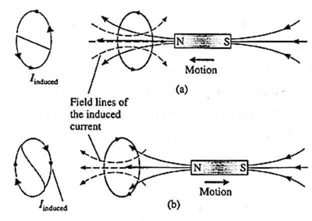
When the magnet is withdrawn, with its N-pole still facing the coil, the number of magnetic lines of induction (pointing left) through the coil decreases.
The induced current reverses its direction to supplement the decreasing flux with its own, as shown in Fig. (b). Facing the coil along the magnet, the induced current is in the clockwise sense. The electric energy in the coil comes from the work done to withdraw the magnet, now against an attractive force.
Thus, we see that Lenz’s law is a consequence of the law of conservation of energy.
Faraday-Lenz’s law of electromagnetic induction in an equation form :
Suppose dφm is the change in the magnetic flux through a coil or circuit in time dt. Then, by Faraday’s second law of electromagnetic induction, the magnitude of the emf induced is
e ∝ dφm/dt or e = k(dφm/dt)
where dφm/dt is the rate of change of magnetic flux linked with the coil and k is a constant of proportionality. The SI units of e (the volt) and dφm/dt (the Weber per second) are so selected that the constant of proportionality, k, becomes unity.
Combining Faraday’s law and Lenz’s law of electromagnetic induction, the induced emf
e = −dφm/dt where the minus sign is included to indicate the polarity of the induced emf as given by Lenz’s law.
This polarity simply determines the direction of the induced current in a closed loop. If a coil has N tightly wound loops, the induced emf will be N times greater than for a single loop, so that
e = −N(dφm/dt)
Causes of induced current on the basis of Lenz’s law :
According to Lenz’s law, the direction of the induced emf or current is such as to oppose the change that produces it. The change that induces a current may be
- (i) the motion of a conductor in a magnetic field or
- (ii) the change of the magnetic flux through a stationary circuit.
In the first case, the direction of induced emf in the moving conductor is such that the direction of the side-thrust exerted on the conductor by the magnetic field is opposite in direction to its motion.
The motion of the conductor is, therefore, opposed.
In the second case, the induced current sets up a magnetic field of its own which within the area bounded by the circuit is
- opposite to the original magnetic field if this field is increasing, but
- is in the same direction as the original field, if the field is decreasing.
Thus, it is the change in magnetic flux through the circuit (not the flux itself) which is opposed by the induced current.
Applications of Lenz's law:
Motion of a Magnet Toward a Loop:
- The magnetic flux through the loop increases when the magnet approaches the loop, and decreases after the magnet has passed through.
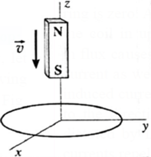
- The induced current in the loop opposes the cause producing the change in flux which, in this case, is the falling magnet. Therefore, the motion of the magnet is opposed, first with a repulsion and then with an attraction.
- The force, in both cases, is upward in the + z-direction.
- The magnetic dipole moment of the falling magnet is directed up. Therefore, looking down the z-axis, the induced current is clockwise when the magnet is approaching the loop, so that the magnetic moment of the loop points down; subsequently, as the magnet recedes, the induced current is anticlockwise.
Jumping Ring Experiment:
The jumping ring experiment by Elihu Thompson is an excellent demonstration of Faraday's laws and Lenz's law of electromagnetic induction.

Jumping Ring : A coil is wound around an iron core that is vertically held upright. On top of the iron core is a metallic ring. After that, a current is turned on to pass through the coil. This causes the ring to jump several metres in the air.
Due to ac, the magnetic field of the solenoid changes continuously. This induces eddy current in the ring. By Lenz’s law, the magnetic field produced by the induced eddy current in the ring opposes the changing magnetic field of the solenoid. Consequently, the two magnetic fields repel each other, making the ring jump.
Q. A circular conducting loop in a uniform magnetic field is stretched to an elongated ellipse as shown below. The magnetic field points into the Page. Will an emf be induced in the loop? If so, state why and give the direction of the induced current.
Ans . Looking in the direction of the magnetic field, there will be an induced current in the clockwise sense.
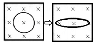
For the same perimeter, the area of a circle is greater than that of an ellipse. Hence, stretching the loop reduces the inward flux through its plane. To oppose this decreasing flux, a current is induced in the clockwise sense so that the field due to the induced current is into the plane of the diagram.
Magnetic flux : The total number of magnetic lines of force passing normally through a given area in a magnetic field, is called the magnetic flux through that area.
Consider a very small area dA in a uniform magnetic field of induction \(\vec{B}\). The area dA can be represented by a vector \(\vec{dA}\) perpendicular to it.
Let θ be the angle between \(\vec{B}\) and \(\vec{dA}\)
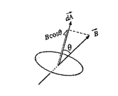
Then, by definition of the magnetic flux through the area dA is
dφm = \(\vec{B}.\vec{dA}\) = B dA cos θ …….(1)
(i) When the magnetic induction is in the direction of the area vector :
i.e. when θ = 0, cos θ = 1
∴ dφm = B(dA),
Thus, the magnetic flux through an area element is maximum, when the magnetic induction is in the direction of the area vector
(ii) When the magnetic induction is perpendicular to the area vector.
i.e. when θ = 90°. cos θ = 0
∴ dφm = 0
Thus, the magnetic flux is minimum, when the magnetic induction is perpendicular to the area vector.
Flux of the Field :
Magnetic flux through a finite area A :
Consider a small area element \(\vec{dA}\) of a finite area A bounded by contour C, see Fig. Suppose this areais situated in a magnetic field \(\vec{B}\) .
In general, the magnetic field may not be uniform over the area A. Then, the magnetic flux through the area element is
dφm = \(\vec{B}.\vec{dA}\) = B dA cos θ
where θ is the angle between B and dA, so that the flux through the area A is
φm = ∫ dφm = \(\int_{A} \vec{B}.\vec{dA}\) = \(\int_{A}\)BdA cos θ
The integration is over the entire area A. can be taken out of the integral if and only if is the same everywhere over A, in which case,
φm = \(\int_{A}\)B(dA) cos θ = B cos θ\(\int_{A}dA\) = BA cos θ
where \(\int_{A}dA\) is just the total area A.
Discuss of Faraday’s second law : The magnetic flux varies with time :
Faraday’s discovery was that the rate of change of flux dφm/dt is related to the work done on taking a unit positive charge around the contour in the reverse direction. This work done is just the induced emf. Accordingly we express Faraday's second law of electromagnetic induction as
|e| = dφm/dt = \(\frac{d}{dt}\)(BA cos θ)
From above Eq., we can see that even if B does not change with time, flux may still vary if the area A changes with time.
If B, A and θ are all constants in time, no emf is induced in the loop. An emf will be induced if at least one of these parameters changes with time.
B and A may change in magnitude; the loop may turn, thereby changing θ.
SI units and dimensions :
(i) Magnetic induction, B :
SI unit : the tesla (T) : 1 T = 1 Wb/m2
Dimensions: [B] = [MT−2I−1].
(ii) Magnetic flux, φm :
SI unit : the Weber (Wb)
Dimensions : [φm] = [B][A] = [MT−2I−1] [L2] = [ML2 T−2I−1]
How Lenz’s law is incorporated into Faraday’s second law of electromagnetic induction by introducing a minus sign :
Explanation :
Consider a conducting loop of area A in a uniform external magnetic field \(\vec{B}\) with its plane perpendicular to the field, i.e., its area vector \(\vec{A}\) is parallel to \(\vec{B}\), see below Fig. We choose the x-axis along \(\vec{B}\), so that \(\vec{B}\) =\(B\hat{i}\) and \(\vec{A}\) =\(A\hat{i}\).

Suppose the magnitude of the magnetic induction increases with time. Then, remaining constant, the induced emf by Faraday-Lenz’s second law of electromagnetic induction is
e = − dφm/dt = \(−\frac{d}{dt}(BA)\) = \(−A\frac{dB}{dt}\) …. (1)
Since we have assumed that B is increasing with time, dB/dt is a positive quantity. Also, A = |\(\vec{A}\)| is positive by definition. Hence, the right hand side of Eq. (1) is a negative quantity.
The right hand rule for area vector fixes the positive sense of circulation around the loop as the clockwise sense. Then, by Lenz’s law the induced current in the loop is in the anticlockwise sense. The sense of the induced emf is the same as the sense of the current it drives. With the clockwise sense fixed as positive, the anticlockwise sense of the induced current is negative. Hence, the sense of e is also negative. That is, the left hand side of Eq. (1) is indeed a negative quantity.
Thus, introducing a minus sign in Faraday’s second law incorporates Lenz’s law into Faraday’s law.
Motional Electromotive Force:
Motional emf : An emf induced in a conductor or circuit moving in a magnetic field is called motional emf.
Translational motion of a conductor:
Motional emf induced in a straight conductor moving in a uniform magnetic field with constant velocity :
Consider a straight wire AB resting on a pair of conducting rails separated by a distance l lying wholly in a plane perpendicular to a uniform magnetic field \(\vec{B}\). \(\vec{B}\) points into the page and the rails are stationary relative to the field and are connected to a stationary resistor R.
Suppose an external agent moves the rod to the right with a constant speed v, perpendicular to its length and to \(\vec{B}\). As the rod moves through a distance dx = vdt in time dt, the area of the loop ABCD increases by dA = l dx = l v dt.

Therefore, in time dt, the increase in the magnetic flux through the loop,
dφm = BdA = Blvdt
By Faraday’s law of electromagnetic induction, the magnitude of the induced emf
e = dφm/dt = \(\frac{Blvdt}{dt}\) = Blv
Motional emf induced in a straight conductor moving in a uniform magnetic field with constant velocity on the Basis of Lorenz force :
Consider a straight rod or wire AB of length l, lying wholly in a plane perpendicular to a uniform magnetic field of induction \(\vec{B}\), as shown in below Fig. \(\vec{B}\) points into the page.
Suppose an external agent moves the wire to the right with a constant velocity \(\vec{v}\) perpendicular to its length and to \(\vec{B}\). The free electrons in the wire experience a Lorentz force (=\(q\vec{v}\) x \(\vec{B}\)).

According to the right-hand rule for cross products, the Lorentz force on negatively charged electrons is downward. The Lorentz force moves the free electrons in the wire from A to B so that A becomes positive with respect to B. Thus, there will be a separation of the charges to the two ends of the wire until an electric field builds up to oppose further motion of the charges.
In moving the electrons a distance l along the wire, the work done by the Lorentz force is
W = Fl = (qvB sin θ)l = qvBl
Since the angle between \(\vec{v}\) and \(\vec{B}\), θ = 90°. Since electrical work done per unit charge is emf, the induced emf in the wire is
e = W/q = vBl
Alternatively, the electric field due to the separation of charges is F/q = \(\vec{v}\)x\(\vec{B}\) . Since \(\vec{v}\) is perpendicular to \(\vec{B}\), the magnitude of the field = vB.
Electric field = \(\frac{\text{p.d.(e) between A and B}}{\text{distanc Ab(l)}}\)
Therefore, the p.d. or emf induced in the wire AB is
e = vBl
Motional emf in a rotating bar:
Suppose a rod of length l is rotated anticlockwise, around an axis through one end and perpendicular to its length, in a plane perpendicular to a uniform magnetic field of induction \(\vec{B}\), as shown in below Fig. \(\vec{B}\) points into the page. Let the constant angular speed of the rod be ω.
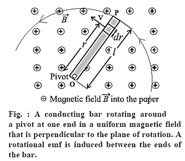
Consider an infinitesimal length element dr at a distance r from the rotation axis. In one rotation, the area traced by the element is dA = 2πrdr.
Therefore, the time rate at which the element traces out the area is
dA/dt = frequency of rotation x dA = fdA
where f = ω/2π is the frequency of rotation.
∴ dA/dt = \(\frac{ω}{2π}(2πrdr)\) = ωrdr
Therefore, the magnitude of the induced emf in the element is
|de| = dφm/dt = B(dA/dt) = Bωrdr
Since the emfs in all the elements of the rod will be in series, the total emf induced across the ends of the rotating rod is
|e|= ∫ de = \(\int_{0}^{l}Bωrdr\)=\(Bω\int_{0}^{l}rdr\)= Bω\(\frac{l^2}{2}\)
For anticlockwise rotation in \(\vec{B}\) pointing into the page, the pivot point O is at a higher potential.
Induced emf in a Stationary Coil in a Changing Magnetic Field:
Experimental Setup :
A permanent bar magnet is mounted on an arc of a semicircle with a radius of 50 cm in a magnet-coil system, as shown in Fig. (a). The arc is part of a rigid aluminium frame and is suspended at the centre of the arc so that the entire system can oscillate freely in its plane. A coil of about 10,000 turns of copper wire loops the arc, allowing the bar magnet to freely pass through it.
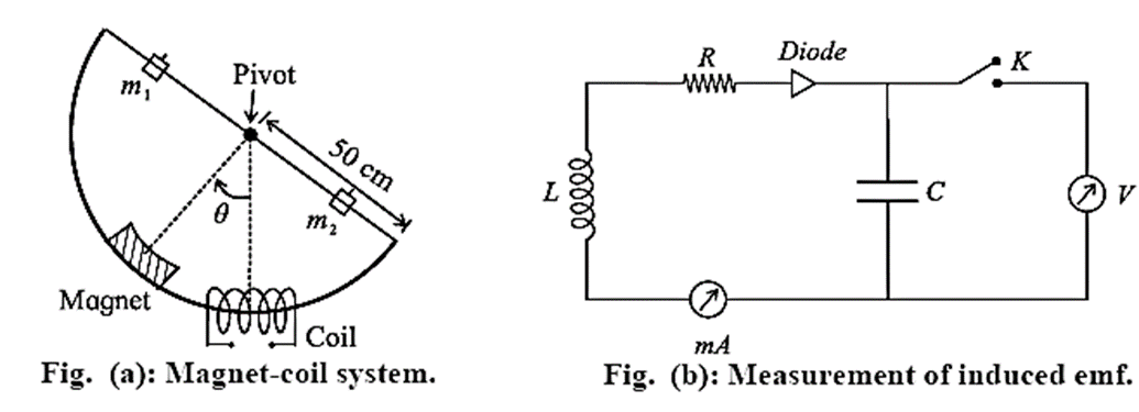
- The magnetic flux through the coil changes as the magnet moves through the coil.
- A capacitor (C) and a diode (D) are connected across the coil to measure the induced emf (Fig. (b)).
- The induced emf generated in the coil is used to charge a capacitor via a diode.
- The voltage generated across the capacitor is then measured.
- Because the time constant (RC) may be greater than the time required to generate the emf in the coil, the capacitor may not be fully charged in a single swing.
- It may take a few oscillations to charge the capacitor to its maximum value, as indicated by the ammeter (mA), which will tell us when the charging current stops flowing.
Graphical representations (flux-time and voltage-time) with the motion of the magnet.

A voltage is induced in the coil as the magnet swings through it in the demonstration of a magnet swinging through a coil.
For the purposes of this discussion, we assume that the magnet's length is less than half that of the coil's length, and that the magnet's North pole swings into the coil from the left. (The induced voltage pulse's polarity is determined by the magnet's polarity.)
We take the magnetic flux linked with the coil to be nearly zero when the magnet is high up away from the coil. As the magnet moves through it the coil and recedes, the magnetic field through the coil increases to its maximum and then decreases. There is a substantial magnetic field at the coil only when it is very near the magnet. Moreover, the speed of the magnet is maximum when it is at the centre of the coil, since it is then at the mean position of its oscillation. Thus the magnetic field changes quite slowly when the magnet is far away and rapidly as it approaches the coil, Fig.(a).
The flux through the coil increases as the north pole approaches the left end of the coil, and reaches a maximum when the magnet is exactly midway in the coil, as shown by the portion bc in Fig. (a).
By Lenz's law, the induced emf will produce a leftward flux that will seek to oppose the increasing magnetic flux of the magnet through the coil.
The interval cd, when the flux is maximum but remains constant and induced emf is zero, corresponds to the situation where the magnet is wholly inside the coil.
Once the magnet swings past the centre of the coil, the flux through the coil starts to decrease — the interval de. To reinforce the decreasing flux of the magnet through the coil, a rightward flux is now induced, thereby flipping the polarity of the induced emf.
If we use a coil that is shorter than the magnet, the time interval cd for which the induced emf remains zero would have been shorter. The times t1 and t2 in Fig. (a) are the points of inflection of the curve, and in Fig. (b) are obviously the minimum and maximum of the induced emf, respectively. The sequence of two pulses, one negative and one positive, occurs during just half a cycle. On the return swing of the magnet, they are repeated in the same order.
Expression for the peak induced emf is directly proportional to the speed of the magnet (or peak induced emf is directly proportional to the angular amplitude and inversely proportional to the time period) :
In the experiment, a magnet is swung through a coil in a radius R. The angular position θ of the magnet is measured from the vertical, the mean position of the swing. The angular amplitude is θ0.
The kinetic energy of the system is ½ Iω2 and the potential energy (relative to the lowest position of the magnet) is MgR(1 − cos θ), where M is mass of the system. Conservation of energy gives, for small θ,
\(\frac{1}{2}I(\frac{dθ}{dt})^2+\frac{1}{2}mgRθ^2\) = constant
Differentiating this, we get
\(\frac{d^2θ}{dt^2}+\frac{MgR}{I}θ\) = 0
i.e., the motion is approximately simple harmonic with a time period
T = 2π\(\sqrt{\frac{I}{MgR}}\)
∴ θ = \(θ_0\,sin\frac{2π}{T}t\)
∴ ω = \(\frac{dθ}{dt}\) = \(\frac{2π}{T}θ_0\,cos\frac{2π}{T}t\)
∴vmax = Rωmax = \(\frac{2π}{T}θ_0R\)
The magnitude of the peak induced emf,
|e| =\(\frac{dΦ_m}{dt}=\frac{dΦ_m}{dθ}.\frac{dθ}{dt}\)
=\(\frac{dΦ_m}{dθ}(2πR\frac{θ_0}{T})\)
=\(\frac{dΦ_m}{dθ}v_{max}\)
as required. The rate of change of flux through the coil is essentially proportional to the velocity of the magnet as it passes through the coil. By choosing different amplitudes of oscillation of the magnet, we can alter this velocity.
Generators:
An electric generator or dynamo converts mechanical energy into electric energy, just the opposite of what an electric motor does.
Principle ; An AC generator works on electromagnetic induction: When a wire coil rotates between two poles of a permanent magnet, an alternating emf is generated in the coil, causing a current to flow when the circuit is closed.
Construction : A simplified diagram of an ac generator is shown in below Fig. It consists of many loops of wire wound on an armature that can rotate in a magnetic field. When the armature is turned by some mechanical means, an emf is generated in the rotating coil. Consider the coil to have N turns, each of area A, and rotated with a constant angular speed ω - about an axis in the plane of the coil and perpendicular to a uniform magnetic field , as shown in the figure. The frequency of rotation of the coil is f = ω/2π Working : The angle θ between the magnetic field and the area of the coil at any instant t is θ = ωt (assuming θ = 0° at t= 0). At this position, the magnetic flux through the coil is φm = N = NBA cos θ = NBA cos ωt As the coil rotates, the changing magnetic flux induces an emf in the coil given by e = − φm/dt = \(−\frac{d}{dt}\)(NBA cos ωt) = − NBA\(\frac{d}{dt}\) (cos ωt) = NBAω sin ωt e = e0 sin ωt, where e0 = NBAω Therefore the induced emf varies as sin ωt and is called sinusoidally alternating emf. In one rotation of the coil, sin ωt varies between + 1 and — 1 and hence the induced emf varies between +e0 and −e0. The maximum value e0 of an alternating emfis called the peak value or amplitude of the emf. The sinusoidal variation of emf with time t is shown in above graph Fig. The emf changes direction at the end of every half rotation of the coil. The frequency of the alternating emf is equal to the frequency f of rotation of the coil. The period of the alternating emf is T = 1/f.


DC generator : A dc generator is much like an ac generator, except that the slip rings at the output are replaced by a split-ring commutator, just as in a dc motor.
The output of a dc generator is a pulsating dc as shown in below Fig.
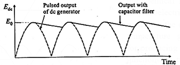
For a smoother output, a capacltor filter is connected in parallel with the output.
| Know This :
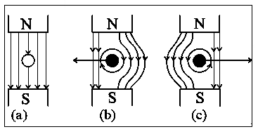
If a wire without any current is kept in a magnetic field, then it experiences no force as shown in figure (a). But when the wire is carrying a current into the plane of the paper in the magnetic field, a force will be exerted on the wire towards the left as shown in the figure (b). The field will be strengthened on the right side of the wire where the lines of force are in the same direction as that of the magnetic field and weakened on the left side where the field lines are in opposite direction to that of the applied magnetic field. For a wire carrying a current out of the plane of the paper, the force will act to the right as shown in figure (c).
|
Back emf and back torque:
Back emf in a motor :
A generator converts mechanical energy into electrical energy, whereas a motor converts electrical energy into mechanical energy. Also, motors and generators have the same construction.
When the input emf rotates the coil of a motor, the changing magnetic flux through the coil induces an emf, which is consistent with Faraday's law of induction.
When a motor's coil rotates, it acts as a generator. This induced emf, according to Lenz's law, opposes any change, so the input emf that powers the motor is opposed by the motor's self-generated emf. This self-generated emf is referred to as a back emf because it opposes the change that caused it.
Q. Why the current through a motor is larger in the beginning than when the motor is running at full speed.
Ans. Initially, when a motor is just starting up, its armature is not turning and hence it is not producing any back emf. As the motor starts speeding up the back emf increases and armature current decreases. This explains the reason as to why the current through a motor is larger in the beginning than when the motor is running at full speed. The effect is noticeable when a high power motor like that of a pump, refrigerator or washing machine is first turned on. The large initial current causes the voltage at the outlets in the same circuit to drop. Due to the IR drop produced in feeder line by the large current drawn by the motor, lights in the same circuit dim briefly.
Back torque in a generator :
In an electric generator, the mechanical rotation of the armature induces an emf in its coil. This is the output emf of the generator. Under no-load condition, there is no current although the output emf exists, and it takes little effort to rotate the armature.
However, when a load current is drawn, the situation is similar to a current-carrying coil in an external magnetic field. Then, a torque is exerted, and this torque opposes the rotation. This is called back torque or counter torque.
Because of the back torque, the external agent has to apply a greater torque to keep the generator running. The greater the load current, the greater is the back torque.
We reply to valid query.