Notes-Part-2
Topics to be Learn : Part-2
|
Power in AC circuit:
Power is defined as the time rate of doing work.
- For a DC circuit, power is measured as a product of voltage and current.
- But since in an AC circuit the values of current and voltage change at every instant the power in an AC circuit at a given instant is the product of instantaneous voltage and instantaneous current.
(a) Average power associated with resistance (power in AC circuit with resistance).
When an alternating emf e = e0 sin ωt is applied to a pure (an ideal) resistor of resistance R, the current through the resistor is i = i0 sin ωt where i0 = e0/R.
Instantaneous power, P = ei = (e0 sin ωt)(i0 sin ωt) = e0 i0 sin2ωt
The average power over one cycle is, by definition,
Pav = \(\frac{\int_{0}^{T}P\,dt}{\int_{0}^{T}dt}\) = \(\frac{e_0i_0}{T}\int_{0}^{T}sin^2ωt\,dt\)
Now, \(\int_{0}^{T}i^2\,sin^2ωt\,dt\) = \(\int_{0}^{T}\frac{1-cos2ωt}{2}dt\)
= \(\int_{0}^{T}\frac{1}{2}dt-\int_{0}^{T}\frac{cos2ωt}{2}dt\)
= \(\frac{T}{2}-\frac{1}{2}(\frac{sin2ωt}{2ω})_{0}^{T}\)
= \(\frac{T}{2}-\frac{1}{4ω}(sin2ωT-sin0)\)
= \(\frac{T}{2}-\frac{1}{4ω}[sin2(\frac{2π}{T})T-0]\)
= \(\frac{T}{2}-\frac{1}{4ω}[0-0]\) = \(\frac{T}{2}\)
∴ Pav = \(\frac{e_0i_0}{T}. \frac{T}{2}\) = \(\frac{e_0}{\sqrt{2}}.\frac{i_0}{\sqrt{2}}=e_{rms}.i_{rms}\)
It is also called as apparent power.
(b) Average power associated with an inductor:
In an AC circuit containing only an ideal inductor, the current i lags behind the emf e by a phase angle of π/2 rad. Here, for e = e0 sin ωt, we have,
i = i0 sin(ωt − π/2)
Instantaneous power,
P = ei = (e0 sin ωt)[i0(sin ωt cos π/2 − cos ωt sin π/2)]
= − e0i0 sin ωt cos ωt (… as cos π/2 =0 and sin π/2 =1)
Average power over one cycle,
Pav = \(\frac{\text{work done in one cycle}}{\text{time for one cycle}}\)
= \(\frac{\int_{0}^{T}P\,dt}{T}\) = \(\frac{-\int_{0}^{T}e_0i_0\,sin\,ωt\,cos\,ωt\,dt}{T}\)
= \(-\frac{e_0i_0}{T}\int_{0}^{T}sin\,ωt\,cos\,ωt\,dt\)
Now, \(\int_{0}^{T}sin\,ωt\,cos\,ωt\,dt\) = \(\frac{1}{2}\int_{0}^{T}sin\,2ωt\,dt\)
= \(\frac{1}{2}[\frac{-cos\,2ωt}{2ω}]_0^T\)
= \(-\frac{1}{4ω}[cos\,2\frac{2π}{T}-cos\,0]\)
= \(-\frac{1}{4ω}[1-1]=0\)
∴ Pav = 0
(c) Average power associated with a capacitor:
In an AC circuit containing only an ideal capacitor, the current i leads the emf e by a phase angle of π/2 rad.
Here, for e = e0 sin ωt, we have, i = i0 sin(ωt + π/2)
Instantaneous power,
P = ei = (e0 sin ωt)[i0(sin ωt cos π/2 + cos ωt sin π/2)]
= e0i0 sin ωt cos ωt (… as cos π/2 =0 and sin π/2 =1)
Average power over one cycle,
Pav = \(\frac{\text{work done in one cycle}}{\text{time for one cycle}}\)
= \(\frac{\int_{0}^{T}P\,dt}{T}\) = \(\frac{\int_{0}^{T}e_0i_0\,sin\,ωt\,cos\,ωt\,dt}{T}\)
= \(\frac{e_0i_0}{T}\int_{0}^{T}sin\,ωt\,cos\,ωt\,dt\)
Now, \(\int_{0}^{T}sin\,ωt\,cos\,ωt\,dt\) = \(\frac{1}{2}\int_{0}^{T}sin\,2ωt\,dt\)
= \(\frac{1}{2}[\frac{-cos\,2ωt}{2ω}]_0^T\)
= \(-\frac{1}{4ω}[cos\,2\frac{2π}{T}-cos\,0]\)
= \(\frac{1}{4ω}[1-1]=0\)
∴ Pav = 0, i.e., the circuit does not dissipate power.
(d) Average power in LCR Circuit:
Let e = e0 sin ωt be the alternating emf applied across the series combination of pure inductor, capacitor and resistor as shown in Fig.
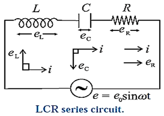
There is a phase difference φ between the applied emf and current given by
i = i0 sin (ωt ± Φ )
Instantaneous power is given by
P = ei = (e0 sin ωt)[ i0 sin (ωt ± Φ )]
= (e0 sin ωt)[i0(sin ωt cos Φ ± cos ωt sin Φ)]
= e0i0 sin ωt (sin ωt cos Φ ± cos ωt sin Φ)
= e0i0 cos Φ sin2ωt ± e0i0 sin Φ sin ωt cos ωt
Average power over one cycle,
Pav = \(\frac{\text{work done in one cycle}}{\text{time for one cycle}}\)
= \(\frac{\int_{0}^{T}P\,dt}{T}\)
= \(\frac{\int_{0}^{T}[e_0i_0cos\,Φ\,sin^2 ωt±e_0i_0sin\,Φ\,sin\,ωt\,cos\,ωt]dt}{T}\)
= \(\frac{e_0i_0}{T}[cos\,Φ\int_{0}^{T}sin^2 ωt±sin\,Φ\int_{0}^{T}sin\,ωt\,cos\,ωt]dt]\)
Now, \(\int_{0}^{T}i^2\,sin^2ωt\,dt\) = \(\int_{0}^{T}\frac{1-cos2ωt}{2}dt\)
= \(\int_{0}^{T}\frac{1}{2}dt-\int_{0}^{T}\frac{cos2ωt}{2}dt\)
= \(\frac{T}{2}-\frac{1}{2}(\frac{sin2ωt}{2ω})_{0}^{T}\)
= \(\frac{T}{2}-\frac{1}{4ω}(sin2ωT-sin0)\)
= \(\frac{T}{2}-\frac{1}{4ω}[sin2(\frac{2π}{T})T-0]\)
= \(\frac{T}{2}-\frac{1}{4ω}[0-0]\) = \(\frac{T}{2}\)
Also
\(\int_{0}^{T}sin\,ωt\,cos\,ωt\,dt\) = \(\frac{1}{2}\int_{0}^{T}sin\,2ωt\,dt\)
= \(\frac{1}{2}[\frac{-cos\,2ωt}{2ω}]_0^T\)
= \(-\frac{1}{4ω}[cos\,2\frac{2π}{T}-cos\,0]\)
= \(\frac{1}{4ω}[1-1]=0\)
Hence Pav = \(\frac{e_0i_0}{T}cos\,Φ×\frac{T}{2}\) = \(\frac{e_0i_0}{2}cos\,Φ\)
= \(\frac{e_0}{\sqrt{2}}.\frac{i_0}{\sqrt{2}}cos\,Φ\)
= \(e_{rms}.i_{rms}cos\,Φ\) = \(e_{rms}.i_{rms}\frac{R}{Z}\)
where the impedance Z = \(\sqrt{R^2+(X_L-X_C)^2}\)
Pav = \(e_{rms}.i_{rms}cos\,Φ\)
- The factor cos Φ is called as power factor. For circuits used for transporting electric power, a low power factor means the power available on transportation is much less than erms.irms. It means there is significant loss of power during transportation.
- This power (Pav) is also called as true power. The average power dissipated in theAC circuit of inductor. Capacitor and resistor connected in series not only depends on rms values of current and emf but also on the phase difference Φ between them.
Power factor cos Φ = R/Z = \(\frac{R}{\sqrt{R^2+(X_L-X_C)^2}}\)
Case :
(i) In a non inductive circuit XL = XC
∴ Power factor cos Φ = R/R = 1 ∴ Φ = 0
∴ Pav = \(e_{rms}.i_{rms}×1\) = \(e_{rms}.i_{rms}\) = \(e_{rms}\frac{e_{rms}}{Z}\) = \(\frac{e_{rms}^2}{Z}\)
(ii) In a purely inductive circuit; Φ = 90°
∴ Power factor = 0
Average power consumed in a pure inductor
Pav = \(e_{rms}.i_{rms}cos\,90^0\) = 0
(iii) In a purely capacitive circuit; Φ = 90°
∴ Power factor = 0
Average power consumed in a ideal capacitor
Pav = \(e_{rms}.i_{rms}cos\,90^0\) = 0
∴Current through pure inductor or ideal capacitor which consumes no power for its maintenance, in the circuit is called idle current or wattless current. Power dissipated in a circuit is due to resistance only.
Wattless current : The current that does not lead to energy consumption, hence zero power consumption, is called wattless current.
In the case of a purely inductive circuit or a purely capacitive circuit, average power consumed over a complete cycle is zero and hence the corresponding alternating current in the circuit is called wattless current.
LC Oscillations :
Oscillations produced using an inductor and a capacitor :
Consider an ideal inductor of inductance L connected to a charged capacitor of capacitance C with an initial charge of q0 via a key K. We assume that the circuit does not include any resistance or a source of emf. At first, the energy stored in the electric field in the dielectric medium between the plates of the capacitor is UE = \(\frac{1}{2}\frac{q_0}{C}\) while the energy stored in the magnetic field in the inductor is zero.
When the key is closed, the capacitor begins to discharge through the inductor and there is a clockwise current in the circuit, as shown in Fig. (a).
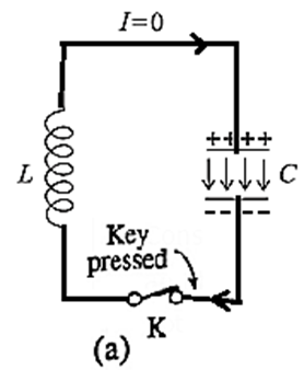
Let q and i are the instantaneous values of charge on the capacitor and current in the circuit, respectively.
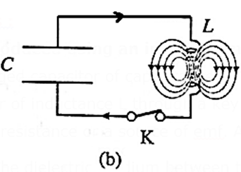
As q decreases, i increases : i = −dq/dt. Thus, the energy UB = ½ Li2 stored in the magnetic field of the inductor increases from zero. Since the circuit is free of resistance, energy is not dissipated in the form of heat, so that the decrease in the energy stored in the capacitor appears as the increase in energy stored in the inductor. As the current reaches its maximum value i0, the capacitor is fully discharged and all the energy is stored in the inductor, Fig. (b).
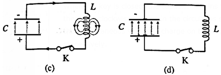
Although q =0 at this instant, dq/dt is nonzero. The current in the inductor then continues to transfer charge from the top plate of the capacitor to its bottom plate, as in Fig. (c). The electric field in the capacitor builds up again, but now in the opposite sense, as energy flows back into it from the inductor. Eventually, all the energy of the magnetic field of the inductor is transferred back into the electric field of the capacitor, which is now fully charged, Fig. (d).
The capacitor then begins to discharge with an anticlockwise current until the energy is completely back with the inductor. The magnetic field in the inductor is in the opposite sense and becomes maximum when the current reaches its maximum minimum value −i0. Subsequently, the current in the inductor charges the capacitor once again until the capacitor is fully charged and back to its original condition.
In the absence of an energy dissipative resistance (ideal condition), this cycle continues indefinitely. When the magnitude of the current is maximum, the energy is stored completely in the magnetic field. When the energy is stored entirely in the electric field, the current is zero. The current varies sinusoidally with time between i0 and −i0. The frequency of this electrical oscillation in the LC circuit is determined by the values of L and C.
LC Oscillations : The energy of the system continuously surges back and forth between the electric field of the capacitor and magnetic field of the inductor. This produces electrical oscillations of a definite frequency. These are called LC Oscillations. If there is no loss of energy the amplitude of the oscillations remain constant and the oscillations are undamped.
Reasons for LC oscillations damped :
- Every inductor has some resistance. This causes energy loss as heat. The amplitude of oscillations goes on decreasing and they finally die out.
- Even if the resistance were zero, total energy of the system would not remain constant. It is radiated away in the form of electromagnetic waves. Working of radio and TV transmitters is based on such radiations.
Electric Resonance:
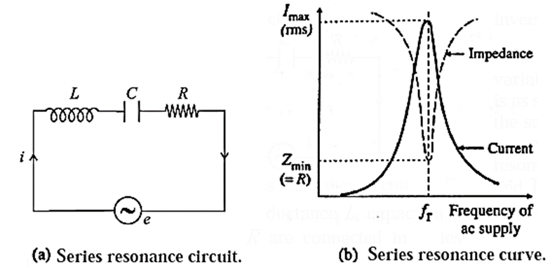
(a) Series resonance circuit:
Electrical resonance in an LCR series circuit : A series LCR resonant circuit is an ac circuit in which a series combination of an inductor, capacitor and resistor is connected to a source of alternating emf.
Suppose a sinusoidally alternating emf e, of peak value so and frequency fl is applied to a circuit containing an inductor of inductance L, a resistor of resistance R and a capacitor of capacitance C, all in series, Fig. (a)
The inductive reactance, XL, and the capacitive reactance, XC, are
XL = ωL and XC = 1/ωC ……(1)
where ω = 2πf.
The rms values irms and erms of current and emf are proportional to one another.
irms = erms/Z ……(2)
where Z = \(\sqrt{R^2+(X_L-X_C)^2}\) = the impedance of the circuit.
The impedance Z drops to a minimum at the frequency fr for which the inductive and capacitive reactances are equal (and opposite, in a phasor diagram); i.e., when
XL = XC ……(3)
Or ωrL = 1/ωrC
Or ωr2 = 1/LC
∴ ωr = \(\frac{1}{\sqrt{LC}}\) ……(4)
Where ωr = 2πfr
∴ fr = \(\frac{1}{2π\sqrt{LC}}\) ……(5)
At this frequency, Z = R and the phase angle Φ = 0, i.e., the combination behaves like a pure resistance, and the current and emf are in phase.
If R is small, the loss is small. Then, the current may be very large. At any other frequency, the impedance is greater than R. If a mixture of frequencies is applied to the circuit, the current only builds‘ up to a large value for frequencies near the one to which the circuit is ’tuned’, as given by Eq. (5).
The resonance curve, Fig. (b), shows the variation of the rms current with frequency. This is an example of electrical resonance.
Equations (3) or (4) give the resonance condition and fr is called the resonant frequency of the LCR series circuit.
At the resonant frequency, the potential differences across the capacitor and inductor are equal in magnitude but in exact antiphase; the current is in quadrature, i.e., 90° out of phase with them, The energy stored in the electric field of the capacitor changes periodically as the square of the potential difference across it; while the energy stored in the magnetic field of the inductor changes periodically as the square of the current. At moments when the potential difference across the capacitor is a maximum and the current through the inductor zero, there is then a maximum of energy stored in the electric field of the capacitor. At moments the potential difference across the capacitor is zero and the current through the inductor a maximum, there is then a maximum of energy stored in the magnetic field of the inductor.
At resonance, the total energy stored in the L-C system is constant, and is simply passed back and forth between the electric and magnetic fields.
When the resonant current is first building up, this energy is drawn from the ac supply. After that, the supply only needs to make up the energy lost as heat in the resistor.
Characteristics of series resonance circuit
1) Resonance occurs when XL = XC
2) Resonant frequency fr = \(\frac{1}{2π\sqrt{LC}}\)
3) Impedance is minimum and circuit is purely resistive.
4) Current has a maximum value.
5) When a number of frequencies are fed to it, it accepts only one frequency (fr) and rejects the other frequencies. The current is maximum for this frequency. Hence it is called acceptor circuit.
Acceptor circuit : An acceptor circuit is a series LCR resonant circuit used in communications and broadcasting to selectively pass a current for a signal of only the desired frequency.
The resonance curve of a series LCR resonant circuit with a small resistance exhibits a very sharp peak at a certain frequency called the resonant frequency fr. For an alternating signal of this frequency, the impedance of the circuit is minimum, equal to R, and the current is maximum. That is, the circuit has a selective property as it prefers to pass a signal of frequency fr and reject those of other frequencies.
Use : A radio or television receiver uses an acceptor circuit to select the desired broadcasting station or channel from among the signals that arrive simultaneously at its antenna. To tune a receiver, the acceptor circuit must be changed so that it resonates at the desired frequency.
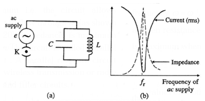
(b) Parallel resonance circuit: A parallel resonant circuit is an ac circuit in which a parallel combination of an inductor and capacitor is connected to a source of an alternating emf.
Consider a capacitor of capacitance C, and an inductor of large self—inductance L and negligible resistance, connected in parallel across a source of sinusoidally alternating emf [Fig. (a)].
Let the instantaneous value of the applied emf be e = e0 sin ωt
Let iL and iC be the instantaneous currents through the inductor and capacitor respectively.
As the current in the inductor lags behind the emf in phase by π/2 radian,
iL = \(\frac{e_0}{X_L}sin(ωt-\frac{π}{2})\) = \(-\frac{e_0}{X_L}cos\,ωt\)
where XL is the inductive reactance.
As the current in the capacitor leads the emf by a phase angle of π/2 radian,
iC = \(\frac{e_0}{X_C}sin(ωt+\frac{π}{2})\) = \(\frac{e_0}{X_C}cos\,ωt\)
where XC is the capacitive reactance.
The instantaneous current drawn from the source is
I = iL + iC = \(e_0(\frac{1}{X_C}-\frac{1}{X_L})cos\,ωt\)
If XL = XC , i = 0. Thus, no current is drawn from the source if XL = XC. In such a case, alternating current goes on circulating in the LC loop, though no current is supplied by the source. This condition is called parallel resonance and the frequency of ac at which it occurs is called the resonant frequency (fr).
The condition for resonance is
XL = XC
ωrL = 1/ωrC
∴ ωr2 = 1/LC
∴ ωr = \(\frac{1}{\sqrt{LC}}\) ……(4)
Where ωr = 2πfr
∴ Resonant frequency, fr = ωr/2π = \(\frac{1}{2π\sqrt{LC}}\) ……(5)
In practice, every inductor possesses some resistance and hence even at resonance, some current is drawn from the source. Also, the resonant frequency is different from that for zero resistence.
The resonance curve shows the variation of current (irms) and impedance with the frequency of the ac supply, Fig. (b). At resonance the current supplied by the source is minimum and the impedance of the circuit is maximum.
Characteristics of parallel resonance circuit
- Resonance occurs when XL = XC.
- Resonant frequency fr = \(\frac{1}{2π\sqrt{LC}}\)
- Impedance is maximum
- Current is minimum.
- When alternating current of different frequencies are sent through parallel resonant circuit, it offers a very high impedance to the current of the resonant frequency ( fr ) and rejects it but allows the current of the other frequencies to pass through it, hence called a rejector circuit.
Rejector circuit : A rejector circuit is a parallel LC resonant circuit used in communications and broadcasting as well as filter circuits to selectively reject a signal of a certain frequency.
The resonant frequency fr is the frequency at which the resonance curve of a parallel resonant circuit with finite resistance of its inductor windings exhibits a sharp minimum. The circuit's impedance is at its maximum for an alternating signal of this frequency and its current is at its lowest.
In other words, the circuit has the ability to selectively pass signals of other frequencies while rejecting signals of frequency fr.
Use : A rejector circuit is used at the output stage of a radio wave transmitter.
| Know This :
Resonance occurs in a series LCR circuit when XL = XC. ω = \(\frac{1}{\sqrt{LC}}\) For resonance to occur, the presence of both L and C elements in the circuit is essential. Only then the voltages L and C (being 180° out of phase) will cancel each other and current amplitude will be e0/R i.e., the total source voltage will appear across. So we cannot have resonance LR and CR circuit. |
Sharpness of Resonance: Q factor
In a series LCR Ac circuit, the amplitude of the current, i.e., the peak value of the current, is
i0 = \(\frac{e_0}{\sqrt{R^2+(ωL-\frac{1}{ωV})^2}}\)
If the angular frequency, ω is changed, at resonance,
ωrL = 1/ωrC
giving ωr = \(\frac{1}{\sqrt{LC}}\)
For ω different from ωr the amplitude of i is less than the maximum value of i0, which is e0/R
Consider the value of ω for which i0 = \(\frac{(i_0)_{max}}{\sqrt{2}}\) = \(\frac{e_0}{R\sqrt{2}}\), so that the power dissipated by the circuit is half the maximum power. This ω is called the half power angular frequency. There are two such values of ω on either side of ωr as shown in Fig.
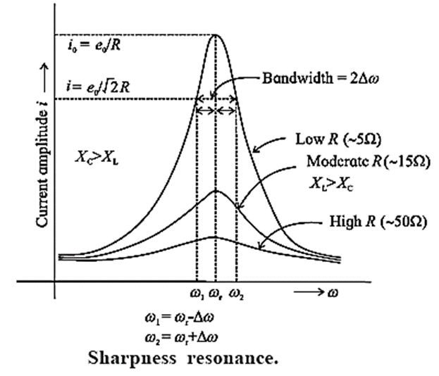
ω1 = ωr − Δω
ω2 = ωr + Δω
∴ ω2 − ω1 = 2Δω. It is called the bandwidth of the circuit. \(\frac{ω_r}{2Δω}\) is a measure of the sharpness of resonance. If it is high, resonance is sharp; if it is low, resonance is not sharp.
The sharpness of resonance is measured by a coefficient called the quality or Q factor of the circuit.
The Q factor of a series LCR resonant circuit is defined as the ratio of the resonant angular frequency to the difference in two angular frequencies taken on both sides of the angular resonant frequency such that at each angular frequency the current amplitude becomes times the value at resonant frequency.
∴ Q = \(\frac{ω_r}{ω_2-ω_1}\) = \(\frac{ω_r}{2Δω}\) = \(\frac{\text{resonant frequency}}{\text{bandwidth}}\)
Q-factor is a dimensionless quantity. The larger the Q-factor, ‘the smaller is the bandwidth i.e., the sharper is the peak in the current. It means the series resonant circuit is more selective in this case.
Above figure shows that the lower angular frequency side of the resonance curve is dominated by the capacitive reactance, the higher angular frequency side is dominated by the inductive reactance and resonance occurs in the middle. This follows from the formulae, XL = ωL and XC = 1/ωC.
The higher the ω, the greater is XL and smaller is XC. At ω = ωr, XL = XC.
Natural frequency of LC circuit :
The natural frequency of LC circuit is \(\frac{1}{2π\sqrt{LC}}\)
where L is the inductance and C is the capacitance.
The reactance of this circuit at this frequency is \(\frac{1}{2πfC-\frac{1}{2πfL}}\) = \(\frac{1}{\frac{2πC}{2π\sqrt{LC}}-\frac{1}{\frac{2πL}{2π\sqrt{LC}}}}\) = \(\frac{1}{\sqrt{\frac{C}{L}}-\sqrt{\frac{C}{L}}}\) = \(\frac{1}{0}\) = ∞
Choke coil : A choke coil is an inductor of high inductance. It consists of a large number of turns of thick insulated copper wire wound closely over a soft iron laminated core. Average power consumed by it over one cycle is
Pav = \(e_{rms}i_{rms}cos\,Φ\)
where the power factor cos Φ = \(\frac{R}{\sqrt{R^2+ω^2L^2}}\)
For ωL >> R, cos Φ is very low implying power consumption is reduced. The energy loss due to hysteresis in iron core is reduced by using a soft iron core.
In an AC circuit, a choke coil is used instead of a resistor to reduce power consumption. In case of a pure resistor Pav is high as it is erms.irms.
| Know This :
The tuning circuit of a radio or TV is an example of LCR resonant circuit. Signals are transmitted by different stations at different frequencies which are picked up by the antenna. Corresponding to these frequencies a number of voltages appear across the series LCR circuit. But maximum current flows through the circuit for that AC voltage which has frequency equal to fr = \(\frac{1}{2π\sqrt{LC}}\) If Q-value of the circuit is large, the signals of the other stations will be very weak. By changing the value of the adjustable capacitor C, the signal from the desired station can be tuned in. |
We reply to valid query.