Notes Part-2
Topics to be Learn : Part-2
|
Resistors :
- A resistor is a device which offers resistance to the flow of electric current through it.
- Resistors are used to limit the current following through a particular path of a circuit.
- Commercially available resistors are mainly of two types : Carbon resistors and Wire wound resistors.
Colour coding on resistor :
An electronic circuit contains many resistors having different resistances. Most of these are carbon film resistors that can be manufactured inexpensively on a large scale.
Because of the mass-production of these resistors and especially their small size, it is not possible to print the resistance value in numerals on the body of the resistor. Hence, a standard colour code has been adopted to indicate the resistance value.
- Three or four coloured rings are marked on the cylindrical body of a resistor.
- Three rings which indicate the resistance value are close to one end, so that the ring closest to the end is considered the first ring.
- Then, the colours of the first two rings indicate the first and second digits in the value of the resistance.
- The colour of the third ring denotes the power of 10.
- A fourth ring, if present, is visibly farther from one end of the resistor than the first ring from the other end.
- The colour of the fourth ring denotes the tolerance in percentage, the maximum amount by which the actual resistance might be different from the marked value and still be acceptable.

Colour code:
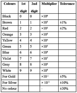
Example :
- Let the colours of the three rings, starting from one end, be green, blue and orange. Green and blue colours represent the first two digits. From the colour code, these digits are 5 and 6 respectively. The third colour, orange, represents 3, so that the multiplier is 103. Thus, the resistance is 56 x 103 Ω = 56 k Ω.
- The colour of the fourth ring represents the percentage tolerance of the resistor, i.e., the percentage error in the value of its resistance.
- For example, if the colour of the fourth ring in the example given above is gold, it means that there may be a 5% error in the value of its resistance. The resistance is, thus, 56000 Ω ± 5 %, i.e., (56000 ± 2800) Ω. i.e., it lies between 53200 Ω and 58800 Ω.
- Absence of the fourth ring means that the tolerance is 20%, i.e., its value may lie within ± 20%, of the colour-coded value.
| Easy Bytes:
To memorize the colour code sequence : “B. B. Roy in Great Britain has Very Good Wife” B B R O Y G B V G W This funny one liner makes it easy to recall the sequence of digits and multipliers. |
Rheostat:
A rheostat shown in Fig. can be used to adjust potential difference between two points in a circuit, change the intensity of lights and control the speed of motors, etc.
Its resistive element can be a metal wire or a ribbon, carbon films or a conducting liquid, depending upon the application. In hi-fi equipment, rheostats are used for volume control.
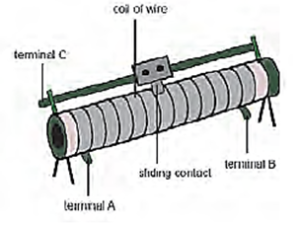
It can also be used as a fixed resistance. Its resistance and current rating is printed on it.
Combination of Resistors:
(i) Series combination of Resistors:
Below Figure shows the circuit diagram for a series combination of three resistors with resistances R1, R2 and R3 connected between points C and D. The ammeter in the circuit measures the (total) current I while the voltmeter measures the potential difference across a resistor.
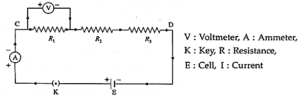
We assume that the ammeter has very low resistance and the voltmeter has very high resistance so that these meters do not change significantly the quantities being measured.
Let V = potential difference (p.d.) between C and D,
V1 = p.d. across the resistor with resistance R1, V2 = p.d. across the resistor with resistance R2 and V3 = p.d. across the resistor with resistance R3.
Then,
V= V1 + V2 + V3 ….(1)
Let R5 = effective (or equivalent or resultant) resistance of the series combination. As the same current I flows through each resistor, we have, by Ohm’s law,
V = IRS and V1 = IR1, V2 = IR2, V3 = IR3
Combining these equations with Eq. (1), we get,
IRS = IR1 + IR2 + IR3
RS = R1 + R2 + R3 …..(2)
If n resistors of resistances R1, R2, ….Rn are connected in series, the effective (or equivalent or resultant) resistance of the combination is
RS = R1 + R2 +....,+Rn = \(\sum \limits_{i=1}^{i=n}R_i\)
Characteristics of a series combination of resistors :
- The same current flows through each resistor.
- The voltage (potential difference) across the combination is equal to the sum of the voltage drops across the individual resistors.
- The effective resistance of the combination is equal to the sum of the individual resistances.
- The effective resistance of the combination is greater than any of the individual resistances.
- The voltage across each resistor is directly proportional to the resistance of the resistor.
- This combination can be used to increase the resistance in a circuit.
(ii) Parallel Combination of Resistors:
- In the parallel combination, the resistors are connected in such a way that the same voltage is applied across each resistor.
- A number of resistors are said to be connected in parallel if all of them are connected between the same two electrical points each having individual path as shown in Fig.
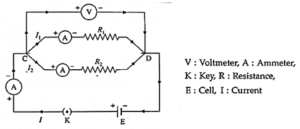
Expression for the equivalent resistance or effective resistance of a parallel combination of resistors :
Above figure shows the circuit diagram for a parallel combination of two resistors with resistances R1 and R2 connected between points C and D. The voltmeter measures the potential difference between C and D and the ammeter measures the current in a given branch.
- We assume that the ammeter has very low resistance and the voltmeter has very high resistance so that these meters do not change significantly the quantities being measured.
Let I = total current in the circuit,
I1 = current through the resistor with resistance R1,
I2 = current through the resistor with resistance R2.
Then,
I = I1 + 12 ...(1)
If RP is the effective (or equivalent or resultant) resistance of the parallel combination, we have, by Ohm’s law.
I = V/ RP and I1 = V/R1, I2 = V/R2
Combining these equations with Eq. (1), we get,
∴ \(\frac{V}{R_P}=\frac{V}{R_1}+\frac{V}{R_2}\)
∴ \(\frac{1}{R_P}=\frac{1}{R_1}+\frac{1}{R_2}\)
If n resistors with resistances R1, R2, ..., Rn are connected in parallel between two common points, the effective (or equivalent or resultant) resistance, RP, of the combination is given by,
\(\frac{1}{R_P}=\frac{1}{R_1}+\frac{1}{R_2}+.......\frac{1}{R_n}\)
Characteristics of a parallel combination of resistors :
- The voltage (potential difference) across each of the resistors is the same.
- The total current is equal to the sum of the currents through the individual resistors.
- The reciprocal of the effective resistance of the combination is equal to the sum of the reciprocals of the individual resistances.
- The effective resistance of the combination is less than any of the individual resistances.
- The current through each resistor is inversely proportional to the resistance of the resistor.
- This combination can be used to decrease the resistance in a circuit.
Specific Resistance (Resistivity) :
Resistivity (specific resistance) : The resistivity (or specific resistance) of a material is (numerically) the resistance of a conductor of the material of unit length and unit area of cross section.
We have, ρ = \(\frac{RA}{l}\)
∴ The SI unit of ρ = ohm.metre2/metre = ohm.metre.
Factors on which the resistance of a metallic conductor depends :
- directly on its length
- inversely on its area of cross section
- on the temperature of the conductor
- on the material of the conductor.
The resistance R of a metallic conductor of a given material at a given temperature is directly proportional to its length l and inversely proportional to its area of cross section A, that is,
R ∝ l or R = ρ \(\frac{l}{A}\)
where the constant of proportionality ρ is called the resistivity (specific resistance), an inherent temperature dependent property of the material of the conductor.
Difference between resistance and resistivity :
| Resistance | Resistivity |
|
|
Electrical conductivity : Reciprocal of electrical resistivity is called electrical conductivity of a material, σ = (ρ)—1.
Note : Resistivity ρ is a property of a material, while the resistance R refers to a particular object. Similarly, the electric field at a point is specified in a material with the potential difference across the resistance, and the current density in a material instead of the current I in the resistor. Then for an isotropic material
ρ = E/J or \(\vec{E}\)=ρ\vec{J}=\frac{\vec{J}}{σ}\) …(for an isotropic material)
σ = \(\frac{ne^2τ}{m}\) for metal
SI unit of σ is: (Ωm)—1 i.e. siemens/meter (Sm—1)
Variation of Resistance with Temperature :
Electrical resistivities of materials, and thus resistances of conductors and resistors, vary with temperature.
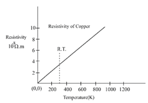
For metals in particular, resistivity is very nearly a linear function of temperature for temperatures above about 178 K (≈ — 95°C).
If ρ0 is the resistivity of a material at a reference temperature T0, and ρ is the resistivity at temperature T,
(ρ — ρ0) ∝ ρ0 (T — T0)
∴ ρ — ρ0 = α ρ0 (T — T0) ….(1)
∴ ρ = ρ0[1 + α ρ0 (T — T0)]
where the proportionality constant α is called the temperature coeflicient of resisiivity, abbreviated as TCR.
The temperature coefficients are commonly specified at 298 K = 25°C; those of pure metals are positive and about 0.004 K—1.
In practice, it is usually more convenient to deal directly with resistance than resistivity. For any particular resistor, resistance is proportional to resistivity, so Eq. (1) gives
R — R0 = α R0(T — T0) …..(3)
∴ R = R0 [1 + α(T — T0)] ….(4)
α is also called the temperature coefficient of resistance.
From (1) and (3),
α = \(\frac{ρ-ρ_0}{ρ_0(T-T_0)}=\frac{R-R_0}{R_0(T-T_0)}\)
Temperature coefficient of resistivity : The temperature coefficient of resistivity is defined as the change (increase or decrease) in resistivity per unit original resistivity at the chosen reference temperature, per degree rise in temperature.
The SI unit of α is the inverse kelvin (K—1).
Temperature coefficient of resistance : The temperature coefficient of resistance is defined as the change (increase or decrease) in resistance per unit original resistance at the chosen reference temperature, per degree rise in temperature. Its SI unit is the inverse kelvin (K—1).
If the temperature difference is small, we can write
α = \(\frac{1}{ρ_0}\frac{dρ}{dT}=\frac{1}{R_0}\frac{dR}{dT}\) …...(5)
Metals and metallic alloys have positive temperature coefficient of resistance (PTC);
their resistivities increase with increasing temperature. Carbon, silicon and germanium have negative temperature coefficient of resistance (NTC); their resistivities decrease with increasing temperature.
Know This :
|
Superconductivity :
|
Electromotive Force (emf) :
Emf of a source of emf : A conductor or an electrical device offers resistance to the passage of current through it, so that energy must be spent to overcome this resistance. This energy is supplied by a source of emf such as a cell or a dynamo.
If dW is the work done by an emf device in taking charge dq through a complete
circuit including the external resistance and the source of emf, the emf of the source is ε = dW/dq
SI unit the joule per coulomb. It is called the volt.
1 volt = 1 joule/coulomb [1 V = 1 J/1 C]
Internal resistance of a source of emf :
- Current flows from the positive terminal of the source to the negative terminal of the external circuit when a resistor is connected across the terminals of an emf source, such as a cell.
- The current moves from the negative terminal to the positive terminal within the source. The movement of charges from the negative terminal to the positive terminal requires some energy to be expended inside the source.
- The content of the source e.g., the electrolytic solution in a cell, resists the flow of the charges. This resistance is called the internal resistance of the source or the cell as the case may be.
- Therefore, as the stored energy in the source of emf (chemical energy in the cell) is converted into electrical energy, a part of the energy is spent in overcoming the internal resistance and the remaining part is available to send the current round the external circuit.
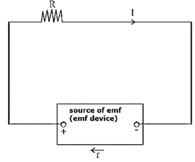
Terminal potential difference of a source of emf : It is the potential difference across its terminals when the source is in a closed circuit.
Suppose that a resistor of resistance R is connected between the terminals of a source of emf, such as a cell, of emf ε and internal resistance r. Let I be the current through the circuit.
In time t, the charge flowing round the circuit = current x time
∴ q = It
Now, ε = dW/dq
∴ dW = ε dq.
Hence, for sending the charge q round the circuit, the total energy supplied by the cell (the work done by the cell) is εq.
If V is the potential difference across the external resistor, the energy spent in sending the charge q through it is Vq.
Let V’ be the potential difference across the internal resistance of the cell. Then the energy spent in sending the charge q through the cell is V’q.
According to the principle of conservation of energy,
energy supplied = energy spent
∴ εq = Vq + V’q
∴ ε = V + V’
Now, V = IR and V’=Ir
∴ ε = IR + Ir = I(R+r)
∴ I = \(\frac{ε}{R+r}\)
V = IR is called the terminal potential difference of the cell when the emf device is in closed circuit. From the equation, ε = IR + Ir = V + Ir, it can be seen that the terminal potential difference of a source of emf is less than the emf of the device as r cannot be zero.
Relation to the emf of a source :
If I = 0, ε = V. Thus, the terminal potential difference of an emf device is equal to its emf, when the device is on open circuit, i.e., when the device is not delivering any current.
[ I = \(\frac{ε}{R+r}\), ∴ Imax = ε/r for R = 0]
Cells in Series :
In a series combination, cells are connected in single electrical path, such that the positive terminal of one cell is connected to the negative terminal of the next cell, and so on.

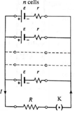
If n identical cells, each of emf ε and internal resistance r, are connected in series :
Suppose n identical cells, each of emf ε and internal resistance r, are connected in series.
Let the current supplied by this combination to an external resistor of resistance R be I.
(i) The equivalent emf of the combination, εeq = ε + ε + …..(n terms) = nε
(ii) The equivalent internal resistance of the combination, req = r + r +… (n terms) = nr
(iii) The terminal potential difference of the combination,
V = εeq — Ireq = n(ε—Ir)
∴ V = n x the terminal potential difference of a single cell
Thus, the terminal potential difference of the series combination of n cells is n times that of a single cell.
Advantages of cells in series.
- The cells connected in series produce a larger resultant voltage.
- Cells which are damaged can be easily identified, hence can be easily replaced.
Cells in parallel :
Here, positive terminals of all the cells are connected together and the negative terminals of all the cells are connected together.

If n identical cells, each of emf ε and internal resistance r, are connected in parallel :
Consider n identical cells, each of emf ε and internal resistance r, connected in parallel as shown in the following figure.
Let the current supplied by the combination to the external resistance R (assumed to be much smaller than the internal resistance of the parallel combination of the cells) be I.
(i) The equivalent emf of the combination is ε
(ii) The equivalent internal resistance r’ of the combination is given by
∴ \(\frac{1}{r'}=\frac{1}{r}+\frac{1}{r}+\)...... (n terms)
∴ \(\frac{1}{r'}=\frac{n}{r}\)
(iii) V = IR is the terminal potential difference across each cell. Hence, the current supplied by each cell is ∴ \(\frac{ε-V}{r}\)
Therefore, the current supplied by the combination to the external resistance is
I = \(\frac{ε-V}{r}\) + \(\frac{ε-V}{r}\) + .... (n terms) = \(n(\frac{ε-V}{r})\)
∴ The current I = n x current supplied by a single cell
Thus, the current supplied by the combination is n times the current supplied by a single cell.
Expression :
Consider two cells with emfs ε1 and ε2, and internal resistances r1 and r2 respectively, are connected in parallel as shown in the following figure.
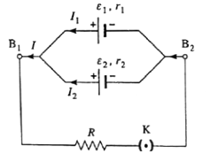
Let VB1 and VB2 be the potentials at points B1 and B2. If V is the potential difference across the cell 1 or cell 2, we have
V= VB1 — VB2 = ε1 — I1r1
∴ I1 = \(\frac{ε_1-V}{r_1}\) and I2 = \(\frac{ε_2-V}{r_2}\)
∴ I = I1 + I2 = \(\frac{ε_1}{r_1}-\frac{V}{r_1}+\frac{ε_2}{r_2}-\frac{V}{r_2}\)
= \((\frac{ε_1}{r_1}+\frac{ε_2}{r_2})-V(\frac{1}{r_1}+\frac{2}{r_2})\)
∴ \(V(\frac{1}{r_1}+\frac{2}{r_2})\) = \((\frac{ε_1}{r_1}+\frac{ε_2}{r_2})-I\)
∴ \(V(\frac{r_1+r_2}{r_1r_2})\) = \(\frac{ε_1r_2+ε_2r_1}{r_1r_2}-I\)
∴ V = \(\frac{ε_1r_2+ε_2r_1}{r_1+r_2}-I(\frac{r_1r_2}{r_1+r_2})\) ….(1)
If the combination of the two cells is replaced by a single cell with emf εeq and internal resistance req, then
V= εeq — Ireq …..(2)
From (1) and (2), we have,
εeq = \(\frac{ε_1r_2+ε_2r_1}{r_1+r_2}\) and req = \(\frac{r_1r_2}{r_1+r_2}\)
→ Thus, \(\frac{1}{r_{eq}}=\frac{1}{r_1}+\frac{1}{r_2}\)
Also, \(\frac{ε_{eq}}{r_{eq}}\) = \(\frac{ε_1r_2+ε_2r_1}{r_1+r_2}×\frac{r_1+r_2}{r_1r_2}\)
∴ \(\frac{ε_{eq}}{r_{eq}}\) = \(\frac{ε_1}{r_1}+\frac{ε_2}{r_2}\)
In general, for n cells connected in parallel,
\(\frac{1}{r_{eq}}=\frac{1}{r_1}+\frac{1}{r_2}+...+\frac{1}{r_n}\)
And \(\frac{ε_{eq}}{r_{eq}}\) = \(\frac{ε_1}{r_1}+\frac{ε_2}{r_2}+......+\frac{ε_n}{r_n}\)
Advantages of cells in parallel :
- For cells connected in parallel in a circuit, the circuit will not break open even if a cell gets damaged or open.
- A larger current can be obtained.
Disadvantages of cells in parallel :
- The voltage developed by the cells in parallel connection cannot be increased by increasing number of cells present in circuit.
Types of Cells :
Electrical cells can be divided into several categories like voltaic cell, primary cell, secondary cell, fuel cell, etc.
- A voltaic cell is a device which converts chemical energy to electrical energy. It consists of two electrodes of different materials, each clipped into an electrolyte. The chemical reactions at the surface of the electrodes produce an emf.
- A primary cell is a voltaic cell in which the chemical reaction producing the emf is not
- When the cell is discharged, it cannot be recharged and becomes useless as a source of emf.
- A secondary cell is a voltaic cell in which the chemical reaction producing the emf is
- When the cell is discharged, it can be recharged by passing a charging direct current through the cell from its positive terminal to its negative terminal. While charging, electrical energy is converted to chemical energy.
- A solar cell is a secondary cell that converts solar energy into electrical energy. A fuel cell is a secondary cell. Here, hydrogen is used as a fuel and the by-product after its burning is water.
- Fuel cells vehicles (FCVs) are electric vehicles that use fuel cells instead of lead acid batteries to power the vehicles. Hydrogen is used as a fuel in fuel cells. The by-product after its burning is water. This is important in terms of reducing emission of greenhouse gases produced by traditional gasoline fueled
- A rechargeable battery or storage battery or accumulator has several secondary cells connected in series which enables it to supply a larger current. The capacity of a rechargeable battery is specified in ampere—hour (symbol Ah), which gives the amount of charge that can be delivered by the battery when freshly charged.
- Examples of secondary batteries: Lead-sulphuric acid, alkaline, nickel-cadmium and lithium-ion.
We reply to valid query.