Notes-Part-2
Topics to be Learn : Part-2
|
Potentiometer:
The potentiometer is a device used for accurate measurement of potential difference as well as the emf of a cell.
- It does not draw any current from the circuit at the null point. Thus, it acts as an ideal voltmeter and it can be used to determine the internal resistance of a cell.
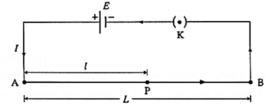
- It consist of a long uniform wire AB of length L, stretched on a wooden board. A cell of stable emf (E), with a plug key K in series, is connected across AB as shown in the following figure.
Potential gradient : Potential gradient is defined as the potential difference (the fall of potential from the high potential end) per unit length of the wire.
- The potential gradient depends upon the potential difference between the ends of the wire and the length of the wire.
- The SI unit of potential gradient is the Volt/meter (V/m)
Potentiometer Principle:
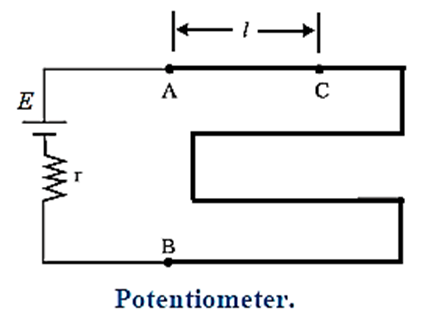
Consider A potentiometer consists of a long wire AB of length L and resistance R having uniform cross sectional area A. (see above Fig.) A cell of emf E having internal resistance r is connected across AB as shown in the Fig. When the circuit is switched on, current I passes through the wire.
Current through AB, I = \(\frac{E}{R+r}\)
Potential difference across AB. VAB = IR
∴ VAB = \(\frac{ER}{R+r}\)
The potential difference (the fall of potential from the high potential end) per unit length of the wire,
\(\frac{V_{AB}}{L}\)=\(\frac{ER}{(R+r)L}\)
As long as E and r remain constant, \(\frac{V_{AB}}{L}\) will remain constant.
\(\frac{V_{AB}}{L}\) is known as potential gradient along AB and is denoted by K.
Thus the potential gradient is calculated by measuring the potential difference between ends of the potentiometer wire and dividing it by the length of the wire.
Let C be any point on the wire between A and B and AC = l = length of the wire between A and C.
Then VAC = Kl
VAC ∝ l as K is constant in a particular case.
Thus, the potential difference across any length of the potentiometer wire is directly proportional to that length. This is the principle of the potentiometer.
Use of Potentiometer:
A) To Compare emf. of Cells :
A battery of stable emf E is used to set up a potential gradient V/L along a potentiometer wire, where V ≡ potential difference across the length L of the wire. The positive terminals of the cells, whose emf’s (E1 and E2) are to be compared, are connected to the high potential terminal A. The negative terminals of the cells are connected to a galvanometer G through a two-way key. The other terminal of the galvanometer is connected to a pencil jockey. The emf E should be greater than both the emf’s E1 and E2.
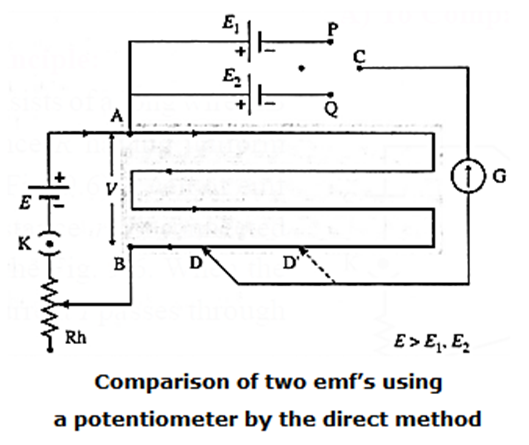
Connecting point P to C, the cell with emf E1 is brought into the circuit. The jockey is tapped along the wire to locate the null point D at a distance l1 from A. Then,
E1 = l1(V/ L)
Now, without changing the potential gradient (i.e., without changing the rheostat setting) point Q (instead of P) is connected to C, bringing the cell with emf E2 into the circuit. Let its null point D’ be at a distance l2 from A, so that
E2 = l2(V/ L)
∴ E1/E2 = l1/l2
Hence, by measuring the corresponding null lengths l1 and l2, E1/E2 can be calculated. The experiment is repeated for different potential gradients using the rheostat.
Remember : This method is used when the two emf’s have comparable magnitudes. Then, the errors of measurement of their balancing lengths will also be of comparable magnitudes.
Method II (sum and difference method ) :
The emfs of cells can be compared also by another method called sum and difference method.
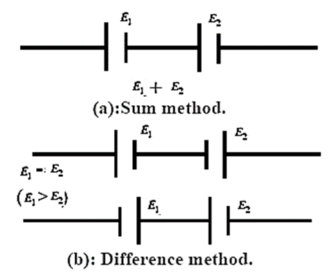
- When two cells are connected so that the positive terminal of the first cell is connected to the negative terminal of the second cell as shown in Fig (a). The emf of the two cells are added up and the effective emf of the combination of two cells is E1 + E2 . This method of connecting two cells is called the sum method. Here, the cells assist each other.
- When two cells are connected so that their negative terminals are together or their positive terminals are connected together as shown in Fig. (b). In this case their emf oppose each other and effective emf of the combination of two cells is E1 – E2 (E1 > E2 assumed). This method of connecting two cells is called the difference method. Remember that this combination of cells is not a parallel combination of cells.
Use of potentiometer to compare the emf's of two cells by the combination method (the sum and difference method) :
Explanation :
A battery of stable emf E is used to set up a potential gradient V/L, along the potentiometer wire, where V ≡ potential difference across length L of the wire.
The positive terminal of the cell 1 is connected to the higher potential terminal A of the potentiometer; the negative terminal is connected to the galvanometer G through the reversing key. The other terminal of the galvanometer is connected to a pencil jockey.
The cell 2 is connected across the remaining two opposite terminals of the reversing key. The other terminal of the galvanometer is connected to a pencil jockey.
The emf E1 should be greater than the emf E2; this can be adjusted by trial and error.

Two plugs are inserted in the reversing key in positions 1—1. Here, the two cells assist each other so that the net emf is E1 + E2. The jockey is tapped along the wire to locate the null point D. If the null point is a distance l1 from A,
E1 + E2 = l1 (V/L)
For the same potential gradient (without changing the rheostat setting), the plugs are now inserted into position 2—2. (instead of 1—1).
The emf E2 then opposes E1 and the net emf is E1 − E2.
The new null point D’ is, say, a distance l2 from A and
E1 − E2 = l2 (V/L)
∴ \(\frac{E_1+E_2}{E_1-E_2}=\frac{l_1}{l_2}\)
∴ \(\frac{E_1}{E_2}=\frac{l_1+l_2}{l_1-l_2}\)
Here, the emf E should be greater than E1 + E2
The experiment is repeated for different potential gradients using the rheostat.
Remember : This method is used when E1 >> E2, So that E1 + E2 and E1 − E2 have comparable magnitudes. Then the errors of measurement of l1 and l2 will also be of comparable magnitudes.
B) To Find Internal Resistance (r) of a Cell:
The internal resistance of a cell is the resistance offered by the electrolyte and electrodes in the cell.
The internal resistance of a cell depends on :
- Nature of the electrolyte : The greater the conductivity of the electrolyte, the lower is the internal resistance of the cell.
- Separation between the electrodes : The larger the separation between the electrodes of the cell, the higher is the internal resistance of the cell. This is because the ions have to cover a greater distance before reaching an electrode.
- Nature of the electrodes.
- The internal resistance is inversely proportional to the common area of the electrodes dipping in the electrolyte.
Experimental set up for this method :
Principle : A cell of emf E and internal resistance r, which is connected to an external resistance R, has its terminal potential difference V less than its emf E.
If I is the corresponding current,
\(\frac{E}{V}=\frac{I(R+r)}{IR}\)=\(\frac{R+r}{R}\)
= \(1+\frac{r}{R}\) ( when R → ∞, v→ E)
∴ r = \(\frac{E-V}{V}R\)
Working : A battery of stable emf E’ is used to set up a potential gradient V/L, along the potentiometer wire, where V ≡ potential difference across the length L of the wire.
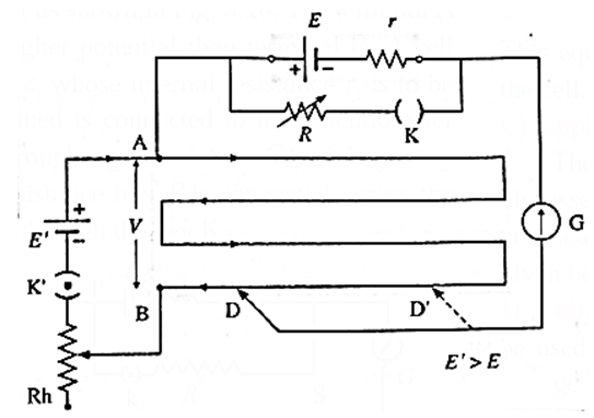
The negative terminal is connected through a centre-zero galvanometer G to a pencil jockey. A resistance box R with a plug key K in series is connected across the cell.
Firstly, key K is kept open; then, effectively, R = ∞. The jockey is tapped on the potentiometer wire to locate the null point D. Let the null length
AD = l1, so that
E = (VAB/L)l1
With the same potential gradient, and a small resistance R in the resistance box, ‘key K is closed.
The new null length AD’ = l2 for the terminal potential difference V is found :
V = (VAB /L)l2
∴ E/V = \(\frac{l_1}{l_2}\) ∴\(\frac{E-V}{V}\)=\(\frac{l_1-l_2}{l_2}\)=\(\frac{l_1}{l_2}-1\)
Now r = \(\frac{E-V}{V}R\)
∴ r = \(R(\frac{l_1}{l_2}-1)\)
R, l1 and l2 being known, r can be calculated. The experiment is repeated with different potential gradients using the rheostat or with different values of R.
C) Application of potentiometer:
The applications of potentiometer discussed above are used in laboratory. Some practical applications of potentiometer are given below.
(i) Voltage divider : The potentiometer can be used as a voltage divider to change the output voltage of a voltage supply.
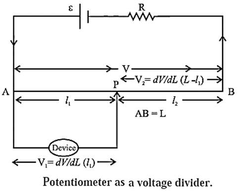
As shown in the Fig. potential V is set up between points A and B of a potentiometer wire. One end of a device is connected to positive point A and the other end is connected to a slider that can move along wire AB. The voltage V divides in proportion of lengths l1 and l2 as shown in the figure.
(ii) Audio control : Sliding potentiometers are commonly used in modern low-power audio systems as audio control devices. Both sliding (faders) and rotary potentiometers (knobs) are regularly used for frequency attenuation, loudness control and for controlling different characteristics of audio signals.
(iii) Potentiometer as a sensor : If the slider of a potentiometer is connected to the moving part of a machine, it can work as a motion sensor. A small displacement of the moving part causes changes in potential which is further amplified using an amplifier circuit. The potential difference is calibrated in terms of the displacement of the moving part.
(iv) To measure the emf (for this, the emf of the standard cell and potential gradient must be known).
(v) To compare the emf’s of two cells.
(vi) To determine the internal resistance of a cell.
Advantages of a Potentiometer Over a Voltmeter:
- Potentiometer is more sensitive than a voltmeter.
- A potentiometer can be used to measure a potential difference as well as an emf of a cell. A voltmeter always measures terminal potential difference, and as it draws some current, it cannot be used to measure an emf of a cell.
- Measurement of potential difference or emf is very accurate in the case of a potentiometer. A very small potential difference of the order 10–6 volt can be measured with it.
- Least count of a potentiometer is much better compared to that of a voltmeter.
Disadvantages of a potentiometer over a volt meter :
- The use of a potentiometer is an indirect measurement method while a voltmeter is a direct reading instrument.
- A potentiometer is unwieldy while a voltmeter is portable.
- Unlike a voltmeter, the use of a potentiometer in measuring an unknown emf requires a standard source of emf and calibration.
Galvanometer:
A galvanometer is a device used to detect weak electric currents in a circuit.
The current may be of the order of a few microamperes, or even a few nano-amperes.
Principle of working : A current carrying coil suspended in a magnetic field experiences a torque which rotates the plane of the coil and tends to maximize the magnetic flux through the coil. The torque due to the spring or the suspension fibre to which the coil is attached tends to restore the coil to its initial position.
When an electric current passes through the coil, it deflects. The deflection is proportional to the current passing through the coil.
Construction of a galvanometer :

- A galvanometer consists of a coil of a large number of turns of fine insulated copper wire wound on a rectangular nonconducting, nonmagnetic frame.
- The coil is pivoted (or suspended) between cylindrically concave pole pieces of a horseshoe strong permanent magnet.
- The coil swings freely around a cylindrical soft iron core fitted between the pole pieces.
- The deflection of the coil can be read with a pointer attached to it. The position of the pointer on the scale provided depends on the current passing through the galvanometer (or the potential difference across it). A galvanometer can be used as an ammeter or a voltmeter with a suitable modification.
- The galvanometer coil has a moderate resistance (about 100 ohms) and the galvanometer itself has a small current carrying capacity (about 1 mA).
Modification to convert a moving coil galvanometer (MCG ) into an ammeter :
To convert an MCG into an ammeter, the modifications necessary are
- Its effective current capacity must be increased to the desired higher value.
- Its effective resistance must be decreased. The finite resistance G of the galvanometer when connected in series, decreases the current through the resistance R which is actually to be measured. In ideal case, an ammeter should have zero resistance.
- It must be protected from the possible damages, which are likely due to the passage of an excess electric current to be passed.
Shunt : In practice to convert a moving coil galvanometer (MCG ) into an ammeter is achieved by connecting a low resistance in parallel with the galvanometer, which effectively reduces the resistance of the galvanometer. This low resistance connected in parallel is called shunt (S).
- Thick bars of manganin are used for shunts because manganin has a very small temperature coefficient of resistivity.
Uses of the shunt:
- It is used to divert a large part of total current by providing an alternate path and thus it protects the instrument from damage.
- It increases the range of an ammeter.
- It decreases the resistance between the points to which it is connected.
- With a shunt of proper value, a galvanometer can be modified into an ammeter of practically any desired range.
Formula to convert a moving coil galvanometer (MCG ) into an ammeter :
The shunt resistance is calculated as follows. In the arrangement shown in the figure,
Let I be the maximum current to be measured and Ig the current for which the galvanometer of resistance G shows a full-scale deflection. Then, the shunt resistance S should be such that the remaining current I — Ig = Is is shunted through it.
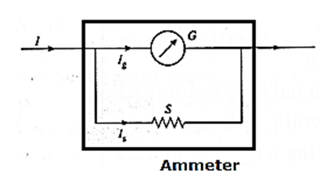
In the parallel combination, the potential difference across the galvanometer
= the potential difference across the shunt
Ig G = Is S
= (I − Ig) S
∴ S = \((\frac{I_g}{I-I_g})G\) ……. (1)
This is the required resistance of the shunt. The scale of the galvanometer is then calibrated so as to read the current in ampere or its submultiples (mA. μA) directly.
(i) If the current I is n times current Ig, then I = nIg. Using this in the above expression we get
S = \((\frac{I_g}{nI_g-I_g})G\)=\(\frac{G}{n-1}\)
This is the required shunt to increase the range n times.
where n = I/Is is the range-multiplying factor, i.e., the current range of the galvanometer can be increased by a factor n by connecting a shunt whose resistance is smaller than the galvanometer resistance by a factor n − 1.
∴ n =\(\frac{G}{S}+1\)= \(\frac{G+S}{S}\)
If RA is the resistance of the ammeter,
RA = \(\frac{GS}{G+S}\)=\(\frac{G}{n}\)
(ii) Also if Is is the current through the shunt resistance, then the remaining current (I – Is) will flow through galvanometer. Hence
G(I – Is) = SIs
∴ GI – GIs = SIs
∴ SIs + GIs = GI
∴ \(\frac{l_s}{l}=\frac{G}{G+S}\)
This equation gives the fraction of the total current through the shunt resistance.
Galvanometer as a Voltmeter:
Modifications required to convert a moving-coil galvanometer into a voltmeter :
- The effective resistance of the galvanometer should be very high. This is because a voltmeter requires a very small current to deflect its pointer. If a large current than this flows through the voltmeter, the voltmeter is said to load the circuit and it will record a much smaller voltage drop.
- The voltage measuring capacity (range) should be increased to a desired value.
- It must be protected from damages which are likely to occur due to an excess applied potential difference.
All these requirements can be fulfilled, if we connect a resistance of suitable high value (Rs) in series with the given MCG.
A series multiplier is made of manganin wire because manganin has a very small temperature coefficient of resistivity.
Formula to Convert a Moving Coil Galvanometer into a Voltmeter.
A moving-coil galvanometer is converted into a voltmeter by increasing its effective resistance by connecting a high resistance RS in series with the galvanometer, see Fig. The series resistance is also useful for changing the range of any given voltmeter.
Let G be the resistance of the galvanometer coil and Ig the current required for a full-scale deflection.
Let V be the maximum potential difference to be measured. The value of the series resistance RS should be such that when the potential difference applied across the instrument is V, the current through the galvanometer is Ig
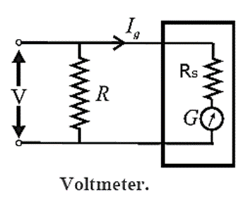
.In the series combination, the potential difference V gets divided across the galvanometer (resistance, G) and the resistance RS :
V = IgG + IgRS = Ig(G + RS)
∴ RS = \(\frac{V}{I_g}-G\)
This is the required value of the series resistance.
The scale of the galvanometer is then calibrated so as to read the potential difference in volt or its submultiples, e.g., mV, directly.
(i) The maximum potential difference Vg that can be dropped across the galvanometer is Vg = IgG. Therefore, the above expression for the series resistance may be rewritten as
RS = \(\frac{VG}{I_gG}-G\) = \(\frac{VG}{V_g}-G\) =G(n-1)
where n = V/Vg is the range-multiplying factor, i.e., the voltage range of the galvanometer can be increased by a factor of n by connecting a series resistance which is (n—1) times the galvanometer resistance.
∴ n = \(\frac{V}{V_g}=\frac{(R_S+G)I_g}{GI_g}\)=\(\frac{R_S+G}{G}\)
Since the resistance of the voltmeter is RV = RS + G,
∴ n = RV/G
∴ RV = Gn
Functions of the series resistance :
- It increases the effective resistance of the voltmeter.
- It drops off a larger fraction of the measured potential difference thus protecting the sensitive meter movement of the basic galvanometer.
- With resistance of proper value, a galvanometer can be modified to a voltmeter of desired range.
Comparison of an ammeter and a voltmeter:
| Ammeter | Voltmeter |
| It measures current | It measures potential difference |
| It is connected in series with a resistance. | It is connected in parallel to a resistance. |
| An ammeter should have very low resistance (ideally zero). | A voltmeter should have very high resistance (ideally infinite). |
| Its range can be increased by decreasing the value of shunt resistance. | Its range can be increased by increasing the value of series resistance. |
| The resistance of an ammeter is
RA = \(\frac{SG}{S+G}=\frac{G}{n}\) |
The resistance of a voltmeter is
RV = G + RS = Gn. |
Thermoelectricity :
Thermoelectric effect :
When electric current is passed through a resistor, electric energy is converted into thermal energy. The reverse process, viz. conversion of thermal energy directly into electric energy was discovered by Seebeck and the effect is called thermoelectric effect.
Seebeck Effect
If two different metals are joined to form a closed circuit (loop) and these junctions are kept at different temperatures, a small emf is produced and a current flows through the metals. This emf is called thermo emf this effect is called the Seebeck effect and the pair of dissimilar metals forming the junction is called a thermocouple. An antimony-bismuth thermo-couple is shown in a diagram.
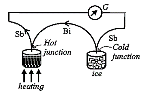
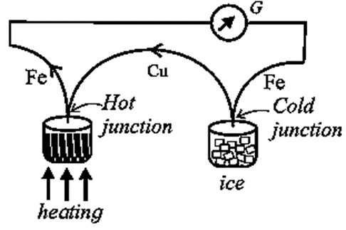
For this thermo couple the current flows from antimony to bismuth at the cold junction. (ABC rule). For a copper-iron couple (see diagram) the current flows from copper to iron at the hot junction.
This effect is reversible. The direction of the current will be reversed if the hot and cold junctions are interchanged.
The thermo emf developed in a thermocouple when the cold junction is at 00 C and the hot junction is at T°C is given by
E = αT + ½ βT2
Here α and β are called the thermoelectric constants. This equation tells that a graph showing the variation of E with temperature is a parabola.
We reply to valid query.