Notes
|
Topics to be learn :
|
Electric current and circuit
Electric current : The electric current is-defined as the rate of flow of electric charge through any section of a conductor.
Electric current = \(\frac{Charge}{Time}\)
- Example : A stream of electrons moving through a conducting wire constitutes an electric current.
- If a charge Q passes through a cross-section of a conductor in time t, then the current I is given by I = Q/t
- The SI unit of electric current is ampere (A).
Electric charge :
- The SI unit of electric charge is coulomb (C).
- 1 coulomb = charge carried by 6.25 x 10⁸
- Electric charge is a scalar quantity.
Conductors : Conductors are the substances through which electric charges can flow easily.
- The electrons of the outer shells of metallic atoms are loosely bound to the nucleus. These electrons are quite free to move. So metals have high electrical conductivity.
- Examples : Metals like copper, silver, aluminium, Graphite, Human body, Acids, Alkalies, Water solution of salts.
Insulators : Insulators are the substances through which electric charges cannot move freely.
- In insulators, the electrons are tightly bound to the nucleus and cannot move away from it. As the electric charges cannot move freely in insulators, so they are poor conductor of electricity.
- Examples : Diamond, Rubber, Glass, Wood, mica, plastic, ebonite, Distilled water
Ampere: If one coulomb of charge flows through any section of a conductor in one second, then current through it is said to be one ampere.
1 ampere = \(\frac{1\,coulomb}{1\,second}\) = 1 Cs-1
The smaller units of current are milliampere and microampere.
1 milliampere = 1 mA = 103 A
1 microampere = 1 pA = 106 A
Know This :
|
Electric circuit: A closed and continuous path along which an electric current flows is called an electric circuit.
- In a torch, a switch provides a conducting link between a battery (a number of cells placed in proper order) and a bulb. When the switch is turned ON, an electric current flows through the bulb and it gives light. Such a continuous and closed path of an electric current is called an electric circuit.
- When the circuit is broken anywhere (or the switch is turned OFF), the current stops flowing and the bulb does not glow.
- An electric circuit through which no current flows is called an open circuit.
- An electric circuit through which current flows continuously is called a closed circuit.
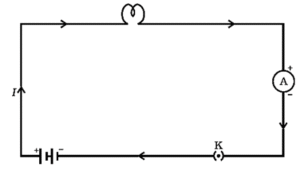
A schematic diagram of an electric circuit comprising – cell, electric bulb, ammeter and plug key
- An electric current flows when there is a potential difference between two points in an electric circuit.
- the electric current flows in the circuit from the positive terminal of the cell to the negative terminal of the cell through the bulb and ammeter.
Ammeter: An ammeter (ampere + meter) is a device used to measure electric current in a circuit.
- As shown in above Fig. an ammeter is always connected in series in a circuit, so that entire current, which we wish to measure, flows through it.
- An ammeter is a low resistance device. When it is connected in series in a circuit, the total resistance of the circuit does not increase appreciably and hence the current in the circuit remains unaffected.
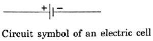
Electrochemical cell or voltaic cell or galvanic cell : Device which converts chemical energy into electric energy is called an electrochemical cell or voltaic or galvanic cell. It is a source used for producing a steady current.
Conventional current and electronic current:
- As shown in Fig. when a conductor AB is connected across the terminals of a cell, free electrons begin to drift or move from its end B (connected to the negative terminal of the cell) to the end A (connected to the positive terminal of the cell).
- The current constituted by flowing electrons is called electronic current. Clearly, the direction of electronic current is from negative terminal to positive terminal.
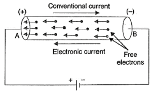
- By convention, the direction of motion of positive charges is taken as the direction of electric current. It is from positive terminal to negative terminal. As the electrons are negatively charged, the direction of conventional current in an electric circuit is taken as opposite to the direction of the flow of electrons.
Electric potential and potential difference :
Potential difference: The potential difference between two points in an electric field is the amount of work done in bringing a unit positive charge from one point to the other.
Potential difference = \(\frac{work\,done}{charge}\) or V = \(\frac{W}{Q}\)
The SI unit of potential difference is joule/coulomb or volt.
Volt: The potential difference between two points is 1 volt if one joule of work is
done in bringing a positive charge of one coulomb from one point to the other point.
1 V = \(\frac{1J}{1C}\)
- Positive charges move from higher to lower potential regions. Electrons, being negatively charged, move from lower to higher potential regions.
- Electric potential of a charge at infinity is zero
Voltmeter: A voltmeter (volt + meter) is a device used to measure potential difference between any two points of a circuit.
As shown in Fig. a voltmeter is always connected in parallel with the component (conductor) at the ends of which we wish to measure the potential difference i.e., voltmeter is connected across the points A and B between which potential difference is to be measured.
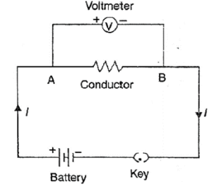
- A voltmeter is a high resistance device. The resistance of a voltmeter is kept very high so that it takes a negligibly small current from the main circuit.
- When it is connected in parallel across any component, it draws very small current from the main circuit and most of the current passes through that component. Hence potential difference (V = IR) across that element is not affected materially.
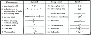
Circuit diagram :
Drawing an electrical schematic diagram, in which the various circuit components are represented by the easily used symbols, is often convenient. (see above fig).
Table provides the standard symbols for some of the most often used electrical components.
Ohm’s law:
Ohm’s law: This law states that the current (I) flowing through a conductor is directly proportional to the potential difference (V) applied across its ends, provided the temperature and other physical conditions remain unchanged.
Mathematically, V ∝ I or V =RI
The proportionality constant R is called the resistance of the conductor.
Resistance: The resistance of a conductor is its property by virtue of which it opposes the flow of current through it. It is equal to the ratio of the potential difference applied across the conductor to the current flowing through it.
Resistance = \(\frac{\text{potential difference}}{current}\) or R = \(\frac{V}{I}\)
- SI unit of resistance is ohm (Ω).
- The resistance of a conductor is said to be 1 ohm if a current of 1 ampere flows through it on applying a potential difference of 1 volt across its ends.
1 ohm = \(\frac{1\,volt}{1\,ampere}\) or 1 Ω = \(\frac{1V}{1A}\)
Graph obtained by plotting potential difference against current through a conductor (V-I graph) :
- V-I graph is a straight line passing through the origin.
- The slope of the V-I graph represents resistance of the conductor.
Example : V–I graph for a nichrome wire.
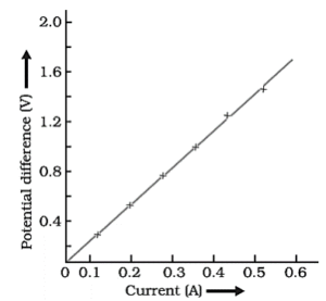
- A straight line plot shows that as the current through a wire increases, the potential difference across the wire increases linearly – this is Ohm’s law.
Resistor : The property by virtue of which a material opposes the flow of current through it is called resistance and any material which has some resistance is called a resistor.
Function of rheostat in an electric circuit : It changes the current in a circuit due to the change in its resistance.
Factors on which the resistance of a conductor depends :
Factors affecting the resistance: At a constant temperature, the resistance of a conductor depends on the following factors:
(i) Length: Resistance R of a conductor is directly proportional to its length L, i.e.,
R ∝ L
(ii) Area of cross-section: Resistance R of conductor is inversely proportional to its area of cross-section A, i.e.,
R ∝ \(\frac{1}{A}\)
(iii) Nature of the material: Resistance also depends on the nature of the material of which the conductor is made. The resistance of a copper wire is much less than that of a nichrome wire of same length and area of cross-section.
Combining the above factors, we get,
R ∝ \(\frac{L}{A}\)
R = \(ρ\frac{L}{A}\)
Resistivity : The proportionality constant ρ is called resistivity or specific resistance which depends on the nature of the material.
In the equation R = \(ρ\frac{L}{A}\) if we take
L = 1m and A = 1 m2
then R = ρ
Hence, resistivity is defined as the resistance offered by a cube of a material of side 1 m when current flows perpendicular to its opposite faces.
SI unit of resistivity is ohm metre.
ρ = \(\frac{R×A}{L}\) = \(\frac{ohm-m^2}{m}\) = ohm-meter (Ω-m)
Classification of solid material on the basis of their resistivity values : Solids can be classified into three categories:
(i) Conductors: Metals and their alloys have low resistivity in the range 10—8 Ω m to 10—6 Ω m. These are known as good conductors of electricity. They offer very low resistance to the flow of current. Copper and aluminium have lowest resistivities.
(ii) Insulators: These are the substances which have large resistivities, more than
104 Ω m. Insulators like glass and rubber have high resistivities in the range of 1012 to 1017 Ω m.
(iii) Semiconductors: These are the substances whose resistivities lie in between those of conductors and insulators i.e., between 10—6 to 104 Ω m. Germanium and silicon are typical semiconductors which are of great importance in chips fabrication.
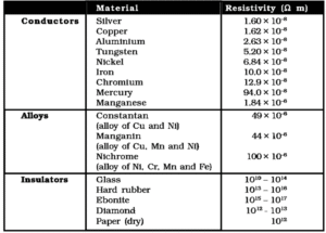
- Alloys have higher resistivity than that of their constituent metals.
- Alloys do not oxidise (or burn) readily at high temperatures.
- Hence the coils of electric toasters and electric irons are made of alloys instead of pure metal
Electrical resistance of a conductor : The electrical resistance of a conductor is its property by virtue of which it opposes the flow of current through it.
Resistance, R = V/I.
- When a low current passes through a conductor for a short duration, its resistance remains constant.
- When a heavy current passes through a conductor for about 30s, its resistance increases due to the increase in its temperature.
Resistance of a system of resistors :
Combination of resistances: In order to obtain a desired value of current in an electrical circuit, a number of resistances have to be used. Resistances can be combined together in the following three ways:
- Series combination.
- Parallel combination.
- Mixed combination.
Equivalent resistance: If a single resistance can replace the combination of resistances in such a manner that the current in the circuit remains unchanged, then that single resistance is called the equivalent resistance.
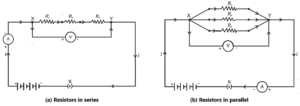
Series combination of resistances: If a number of resistances are joined end to end so that the same current flows through each of them in succession, then the resistances are said to be connected in series.
As shown in above Fig (a) consider three resistances R1 R2 and R3 connected in series. Suppose a current I flows through the circuit when a cell of voltage V is connected across the combination.
By Ohm’s law, the potential differences across the three resistances will be,
V1 = IR1, V2 = IR2, V3 = IR3
If RS, be the equivalent resistance of the series combination, then on applying a potential difference V across it, the same current I must flow through it. Therefore,
V= IRS
But V = V1 + V2 + V3
∴ IRS = IR1 + IR2 + IR3
or RS = R1 + R2 + R3
Laws of resistances in series :
- Current through each resistance is same.
- Total voltage across the combination = Sum of the voltage drops.
- Voltage drop across any resistor is proportional to its resistance.
- Equivalent resistance = Sum of the individual resistances.
- Equivalent resistance is larger than the largest individual resistance.
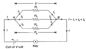
Parallel combination of resistances: If a number of resistances are connected in between two common points so that each of them provides a separate path for current, then they are said to be connected in parallel.
As shown in Fig. consider three resistances R1 R2 and R3 connected in parallel.
Suppose a current I flows through the circuit when a cell of voltage V is connected across the combination. The current I at point A is divided into three parts I1 I2 and I3 through the resistances R1 R2 and R3 respectively. These three parts recombine at point B to give the same current I.
∴ I = I1 + I2 + I3
As all the three resistances have been connected between the same two points A and B, so voltage V across each of them is same. By Ohm’s law,
I1 = \(\frac{V}{R_1}\), I2 = \(\frac{V}{R_2}\), I3 = \(\frac{V}{R_3}\)
If RP be the equivalent resistance of the parallel combination, then.
I = \(\frac{V}{R_p}\)
But I = I1 + I2 + I3
∴ \(\frac{V}{R_p}\) = \(\frac{V}{R_1}\) + \(\frac{V}{R_2}\) + \(\frac{V}{R_3}\)
Or \(\frac{1}{R_p}\) = \(\frac{1}{R_1}\) + \(\frac{1}{R_2}\) + \(\frac{1}{R_3}\)
Laws of resistances in parallel :
- Voltage across each resistance is same and is equal to the applied voltage.
- Total current = Sum of the currents through the individual resistances.
- Currents through various resistances are inversely proportional to the individual
- Reciprocal of equivalent resistance = Sum of reciprocals of individual resistances.
- Equivalent resistance is less than the smallest individual resistance.
Advantages of connecting electrical devices in parallel with the battery:
- Each device gets the full battery voltage.
- The parallel circuit divides the current through the electrical devices. Each device gets proper current depending on its resistance.
- If one device is switched OFF/ON, others are not affected.
Heating effect of electric current :
The phenomenon of production of heat in a resistor by the flow of an electric current through it is called heating effect of current or Joule heating.
Joule’s law of heating: It states that the amount of heat produced in a conductor is directly proportional to
- the square of current I through it
- proportional to its resistance R and
- the time ¢ for which the current is passed.
Mathematically,
H = I2Rt Joule = \(\frac{I^2Rt}{4.18}\) cal
Derivation of Joule’s law of heating: As shown in below Fig. consider a resistor AB of resistance R connected across a cell of voltage V. Suppose a current I is flowing through it.
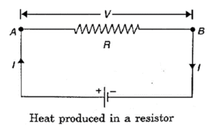
The amount of charge that flows from A to B in time t is given by
Q = I x t …[ I = Q/t)
By definition of potential difference, the work done in carrying unit charge from A to
B = V
∴ Work done in flowing charge Q from A to B is
W =V x Q = V x It
This energy is spent in overcoming the resistance offered by the resistor. If whole of the energy appears as heat, then the amount of heat produced is
H = VIt joule = I2Rt joule …[‘.’ V = IR]
H = \(\frac{VIt}{4.18}\) = \(\frac{I^2Rt}{4.18}\) ……[1 cal = 4.18 joule]
The above equations represent Joule’s law of heating.
Applications of heating effect of electric current:
Household heating appliances:
- Most of the electrical appliances used in daily life are based on heating effect of current such as room heater, electric toaster, electric iron, electric oven, electric kettle, geyser, etc.
- The heating element used in these appliances should have high melting point and high resistivity.
- As compared to pure metals, alloys have higher resistivity.
In most of the household heating appliances, nichrome element is used because of the following reasons:
- Its melting point is high.
- Its resistivity is large.
- It can be easily drawn into thin wires.
- It is not easily oxidised by the oxygen of the air when heated.
Incandescent electric bulb:
- It is an important application of Joule heating effect.
- It consists of a filament of a fine metallic wire enclosed in a glass bulb filled with chemically inactive gases like nitrogen and argon.
- The filament material should have high resistivity and high melting point. Therefore, tungsten (melting point 3380°C) is used for bulb filament.
- When a current is passed through the filament, it gets heated to a high temperature and emits light.
Electric fuse:
- It is a safety device used to protect electrical appliances from strong A fuse wire must have high resistivity and low melting point. It is usually made from an alloy of tin and lead. It is put in series with the live wire of the circuit. When the current exceeds the safety limit, the fuse wire melts and breaks the circuit. The electric installations are thus saved from getting damaged.
- The fuses used for domestic purposes are rated as 1 A, 2 A, 3 A, 5 A, 10 A etc. For an electric iron which consumes 1 kW electric power when operated at 220 V, a current of (1000/220) A, that is, 4.54 A will flow in the circuit. In this case, a 5 A fuse must be used.
Electric power :
Electric energy: It is defined as the total work done in maintaining an electric current in an electric circuit for a given time.
A conductor offers resistance to the flow of current. So work has to be done continuously to maintain it. The work done in carrying a charge Q through a potential difference V is,
W = V x Q
But Q = I x t
∴ W = VIt = I2Rt …[‘.’ V = IR]
This work done is the electric energy consumed in the circuit in time t
∴ Electric energy = VIt = I2Rt
Thus, the electric energy consumed depends on the square of current I, resistance R and time t.
Electric power: The electric power of an appliance is the rate at which it consumes electric energy. Or it is defined as the rate at which work is done in maintaining an electric current in an electric circuit.
When a current I flows through a circuit for a time t at a constant potential difference V, then the work done is,
W = VIt joule
∴ Electric power, P = \(\frac{W}{t}\) = \(\frac{VIt}{t}\) = VI
Or P = VI = I2R = \(\frac{V^2}{R}\) ….[ ‘.’ I = V/R]
Electric power = Voltage x Current.
- The expression: P = I2R holds when current I remains constant.
- The expression: P = \(\frac{V^2}{R}\) holds when potential difference V remains constant.
SI unit of electric power is watt. The power of an appliance is said to be one watt if a current of 1 ampere flows through it on applying a potential difference of one volt across it.
1 watt = 1 volt x 1 ampere.
Watt-hour: It is defined as the electric energy consumed by an appliance of 1 watt
in one hour.
1 watt-hour = 1 watt x 1 hour = \(\frac{1J}{1s}\) x 3600 s = 3600 J.
Kilowatt-hour: It is defined as the electric energy consumed by an appliance of 1000 watt in one hour.
1 kilowatt-hour =1 kilowatt x 1 hour = 1000 watt x 3600 second
= 3.6 x 10⁶ watt second
or 1 kWh =3.6 x 10⁶ J
The commercial unit of electric energy is kilowatt hour (kWh). In our electricity bills, 1 kWh is taken as one unit.
We reply to valid query.